Design Guide | iC7 Series Liquid-cooled System Modules
7 Electrical Installation
7.1 Fuses of the Drive System
The drive system must be equipped with ultra-rapid AC fuses to limit the damage of the drive system. The fuse sizes are based on Mersen
aR fuses. Use these fuses to achieve sufficient protection against short circuits. Select the supply cable protection according to local
regulations.
DC fuses must be installed for parallel units where necessary to limit the damage of the drive system. Each DC supply line must be
equipped with fuses. The DC fuses are provided with the delivery as option. Do not replace the DC fuses with any other types.
The protective devices must be integrated within the same overall assembly as the system module.
The fuse tables can be found in 10.5.1 List of Fuse Size Information.
Fuse ratings are based on a maximum ambient temperature of 60 °C and a minimum airflow of 2 m/s around the fuse.
To ensure fuse performance, make sure that available supply short circuit current is sufficient. See minimum required values (I
cp,mr
) at the
fuse location in 10.5.2 AC Fuses for AFE or GC 525–690 V AC, IP00/Open Type.
7.2 Guidelines for DC Connections of System Modules
The DC busbars and cabling must be dimensioned according to local installation regulations and codes, so that the cross-section is
sufficiently large for the current flowing at the relevant point. See the DC current ratings in 10.6.1 List of Current Rating Information.
The DC busbar itself must be designed to attain the lowest possible inductance.
Adequate fuse protection for the drive configuration must be provided on the line side and on the DC side. The power cables and
busbars must be dimensioned with sufficient thermal and mechanical strength to handle short circuits in the system. See the fuse ratings
in 10.5.1 List of Fuse Size Information.
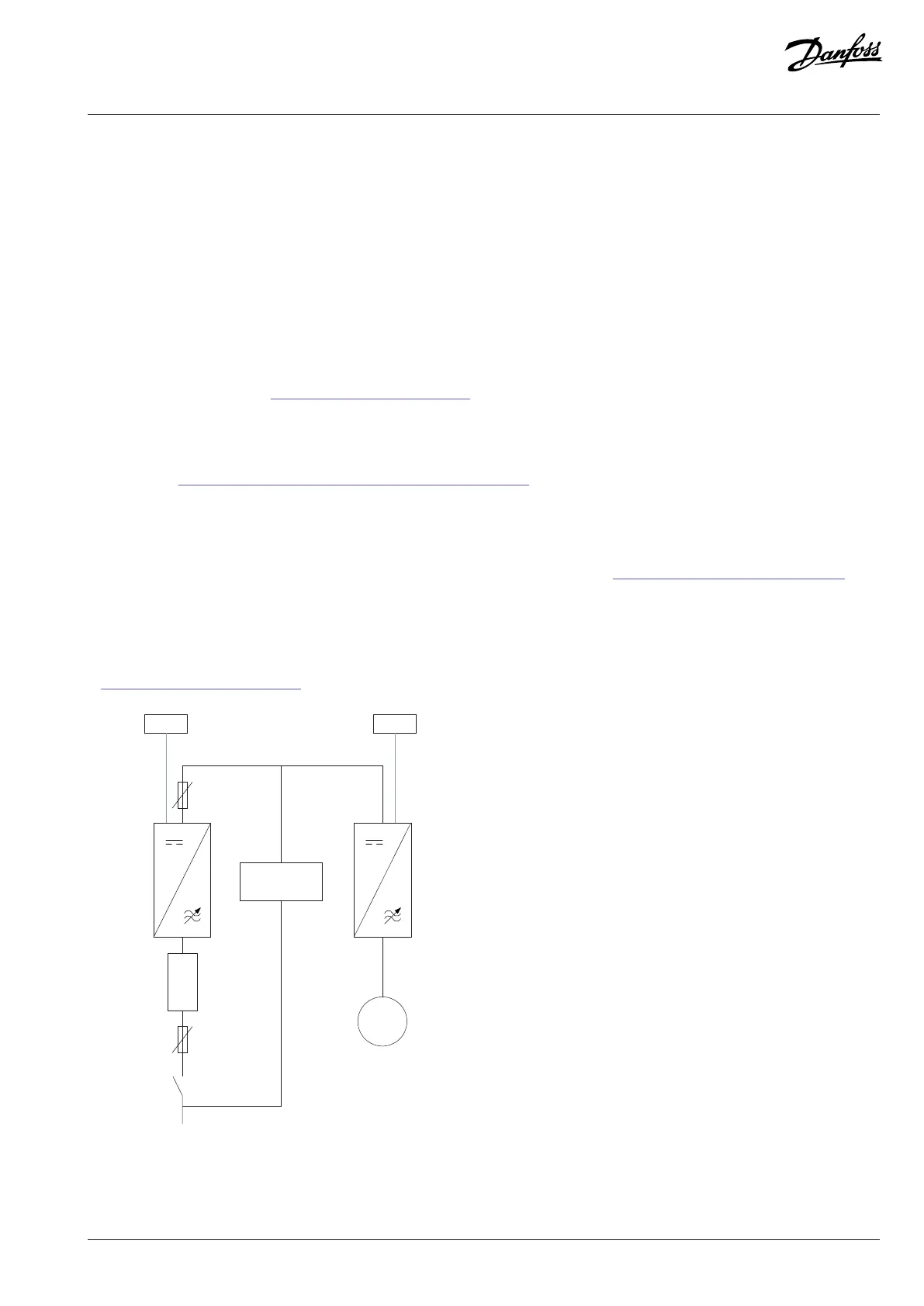
INU
power
unit
Pre-charging
circuit
Figure 56: DC Connections of Single Power Units
Danfoss Drives Oy © 2024.03 AJ475942178716en-000101 / 172K2848A | 65
 Loading...


