Design Guide | iC7 Series Liquid-cooled System Modules
9. If the product label plate was removed from power unit 1, mount it on the new power unit.
a. Mount the product label plate with a M4x8 screw (141N2502). Use a TX20 bit to tighten the screw to torque 2 Nm (18 in-lb).
See Figure 116.
9.7 Draining the System Modules
9.7.1 Draining the System Modules, System Modules with Integration Units, and Filters
Always drain the system modules and filters before storage or transportation.
Required for the draining procedure:
l Container large enough for the drained coolant. One system module can hold 0.55 l of coolant.
l Pressurized air can be used for the draining. Maximum pressure is 5 bar.
l Dust caps or tape.
1. Close the valves of the system module to be drained.
2. Place the container below the coolant inlet and outlet.
3. Disconnect the coolant outlet and inlet hoses from the main manifold and drain the coolant to the container.
4. To drain all the coolant from the module, supply pressurized air to the outlet connector.
5. After all the coolant is drained, remove the system module from the cabinet.
6. Before storage or transportation, plug the coolant inlet and outlet connectors.
Use the dust caps delivered with new system modules, or if not available, use tape.
7. Dispose of the coolant according to local laws and regulations.
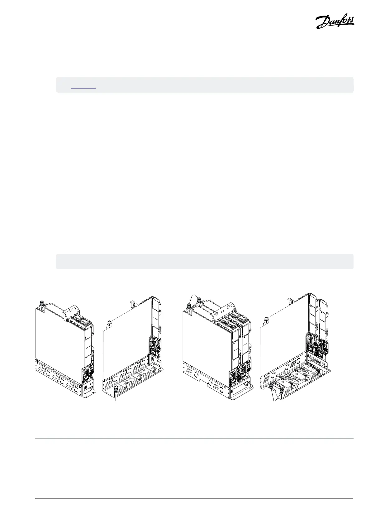
Figure 123: Inlet and Outlet Connectors of System Modules xM10L and xM12L
1 Outlet connectors 2 Inlet connectors
Danfoss Drives Oy © 2024.03 AJ475942178716en-000101 / 172K2848A | 123
 Loading...


