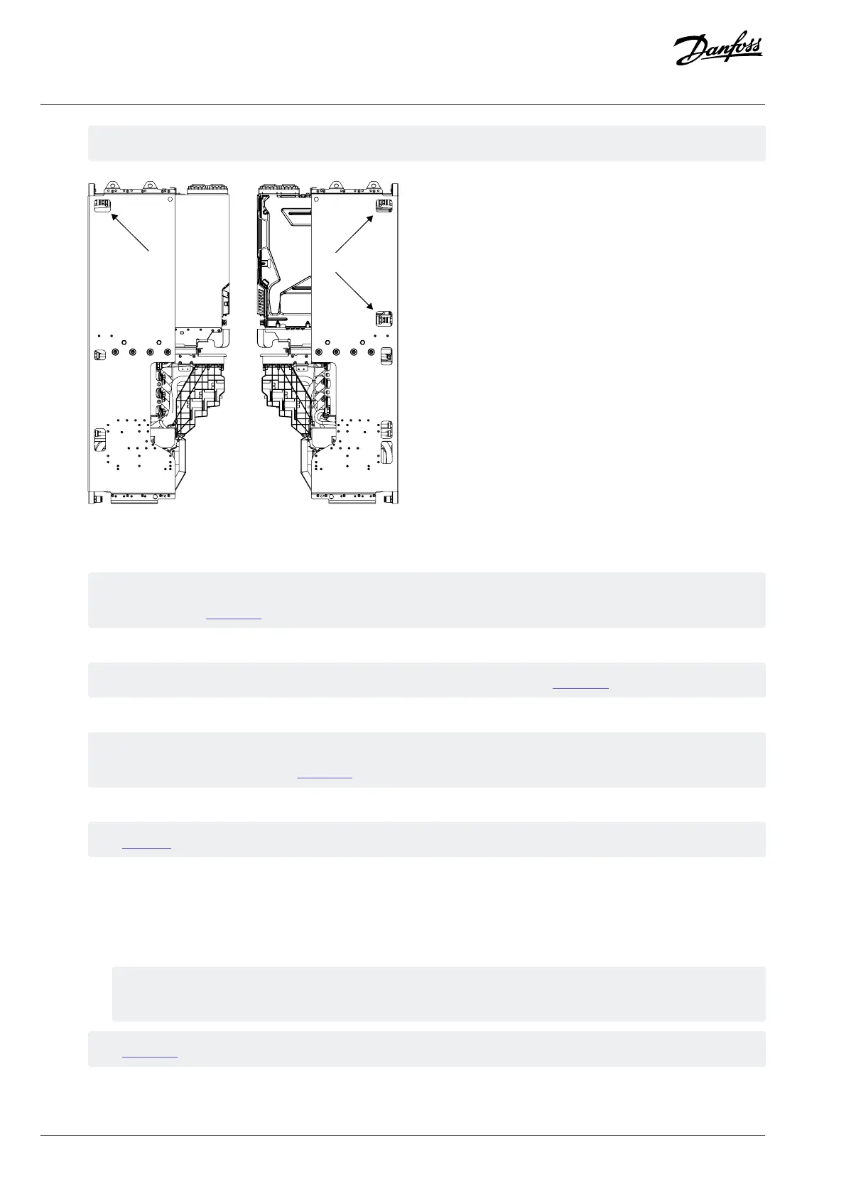
The cooling connectors are visible from the sides of the integration unit.
Figure 122: Cooling Connectors on the System Module
3. Slide up the module locking plate and fix it on the system module.
Tighten the 5 size M6x16 screws (141L3015) on the module locking plate. Use a TX30 bit and tighten the screws to torque
5 Nm (44 in-lb). See Figure 120.
4. Mount the system module on the integration unit with 2 size M6x16 screws (141L3015) at the top part of the system module.
Use a TX30 bit to mount the screws. Tighten the screws to torque 5 Nm (44 in-lb). See Figure 119.
5. Release the handle on the front of the system module and install it so that it is facing the module.
The handle is mounted with two 6x12 screws (141N2374). Use a TX30 bit to release and mount the screws. Tighten the
screws to torque 5 Nm (44 in-lb). See Figure 118.
6. Install DC fuses on the DC busbars. Use two M10x25 screws (141L3598) on each fuse.
See Figure 67.
7. Connect the cables on the system module.
a. Connect the optical fiber cable to control terminal X81.
b. Connect the AuxBus cable to terminal X79.
c. Connect the power cables.
Mount the power cables with M10x30 mounting bolts (141N9277). Use a 17 mm (0.67 in) bit to tighten the bolts to
torque 35 Nm (310 in-lb).
See Figure 117.
8. Check that the cables are not pinned between the system module and the frame of the integration unit.
122 | Danfoss Drives Oy © 2024.03 AJ475942178716en-000101 / 172K2848A
Design Guide | iC7 Series Liquid-cooled System Modules
 Loading...


