Design Guide | iC7 Series Liquid-cooled System Modules
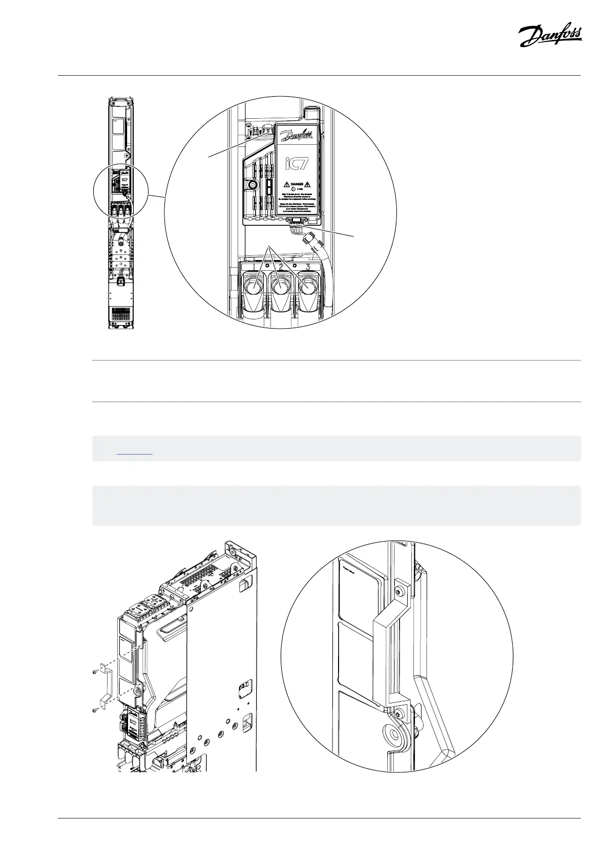
Figure 117: Disconnecting the Cables from the System Module
1 Control terminal X81 2 AuxBus terminal X79
3 Power cable mounting bolts
3. Release the fuses from the DC busbars. Remove the two M10x25 screws (141L3598) from each fuse.
See Figure 67.
4. Release the handle on the front of the system module and install it so that it can be used to move the module.
The handle is mounted with two 6x12 screws (141N2374). Use a TX30 bit to release and mount the screws. Tighten the
screws to torque 5 Nm (44 in-lb).
Figure 118: The Handle on the System Module
Danfoss Drives Oy © 2024.03 AJ475942178716en-000101 / 172K2848A | 119
 Loading...


