EasyManuals Logo

Danfoss iC7 Series Design Guide

Danfoss iC7 Series
224 pages
To Next Page IconTo Next Page
To Previous Page IconTo Previous Page
Page #164 background imageLoading...
Page #164 background image
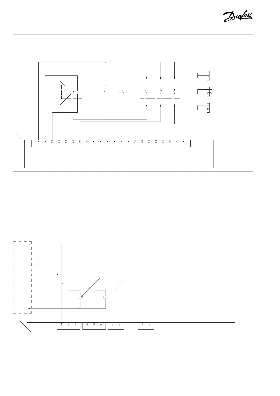
10.3.9 Pre-charging Control Circuit
X13
36
GND
22
DO2
23
GND
24
GND
17
DI5
37
GND
33
AI1
31
AO1
32
+10Vref
21
DO1
14
DI2
15
DI3
16
DI4
13
DI1
12
24VDC
11
24VDC
19
DGND
20
GND
34
AI2
35
GND
38
GND
18
DI6
0
ENABLE
13
14
-SF11
AUTO
MANUAL
13
14
-SF12
STOP
START
13
14
-SF
23
24
13
14
-SF11
13
14
-SF
13
14
-SF12
13
14
M
14
C
11
12
T
M1M2
T1T2
C1
C2
13
A B D E F G
K
J
H
I
e30bg433.10
A AFE or GC remote control start/stop B Mains 0-enable
D Pre-charging man-auto E Main input device status
F Main input device tripped (circuit breaker) G Cooling supervision
H Status/supervision I I/O and Relay Option
J AFE start/stop K Field connection
Figure 166: Pre-charging Control Circuit Diagram
X101
X102 X103 X51
71
TI+
72
TI-
1
COM
2
NO
3
NC
4
COM
5
NO
6
NC
8
NO
7
COM
A1
A2
A1
A2
23
24
-SF11
115–
230 VAC
N
A B
F
C D
E
e30bh742.11
Figure 167: Pre-charging Control Circuit Diagram
164 | Danfoss Drives Oy © 2024.03 AJ475942178716en-000101 / 172K2848A
Design Guide | iC7 Series Liquid-cooled System Modules

Table of Contents

Other manuals for Danfoss iC7 Series

Questions and Answers:

Question and Answer IconNeed help?

Do you have a question about the Danfoss iC7 Series and is the answer not in the manual?

Danfoss iC7 Series Specifications

General IconGeneral
Product TypeMedia Converter
Power Supply24 VDC
Housing MaterialPlastic
MountingDIN Rail
ManufacturerDanfoss
Protection ClassIP20
Protocols SupportedModbus
Humidity5% to 95% (non-condensing)
Weight150 g
SeriesiC7 Series

Related product manuals