8.4 Control Board Connections
Table 22: Control Board Connections
Terminal Function Connector type
X1 Ethernet port (used for fieldbus) RJ45
X2 Ethernet port (used for fieldbus) RJ45
X0 Ethernet port (used for the PC tool) RJ45
Micro SD microSD card Micro SD
X62 24 V DC supply 2 x 3 spring force connector 0.2–1.5 mm
2
X33 for inverter module STO terminal 1 x 10 spring force connector 0.2–1.5 mm
2
Option bus Option bus (internal connection) Custom
X80 Fiber optic link to power unit or star coupler board LC-duplex
X9 Control panel terminal iX Industrial
RTC battery RTC battery BR1632 (battery type)
44
45
45
46
47
48
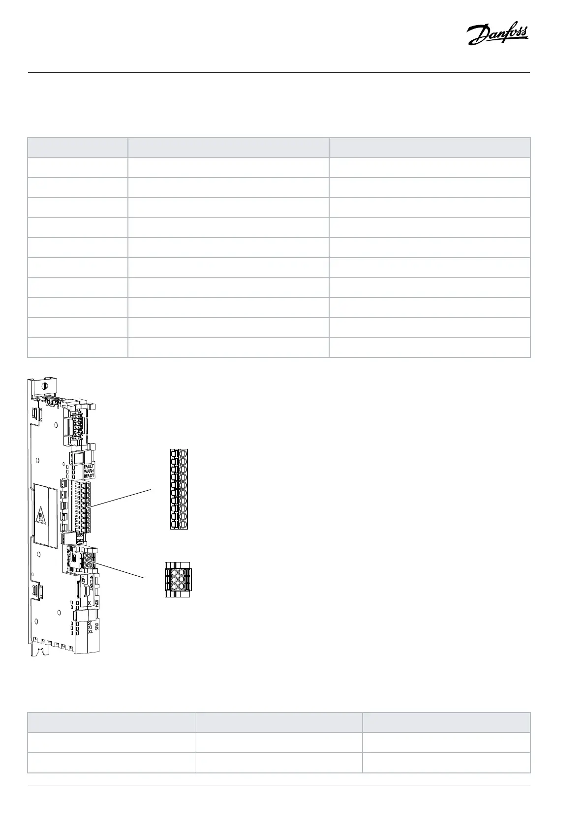
X33
101
61
63
102
62
64
X62
Figure 98: Control Board Terminal Block and Terminal Numbering
Table 23: STO Terminal Signals (X33) for the Inverter Module
Terminal Function Description
41A
(1)(1)
24 V + 24 V DC Output
41B
(1)
24 V + 24 V DC Output
96 | Danfoss Drives Oy © 2024.03 AJ475942178716en-000101 / 172K2848A
Design Guide | iC7 Series Liquid-cooled System Modules
 Loading...


