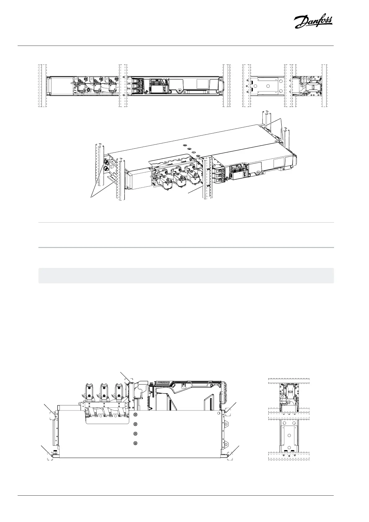
Figure 18: Mounting Holes of the System Module with the Integration Unit in Horizontal Position
1 Mounting holes 2 View from the front
3 View from the bottom
3. Attach the system module to the mounting brackets of the cabinet.
The mounting brackets are not included in the delivery.
5.3.4.3 Installing System Modules with Integration Units into a Cabinet on their Backsides
1. Install the system module into the cabinet on its backside.
2. Use mounting holes to attach the system module into the cabinet.
a. For aluminum parts, use M6 grade 8.8 screws with a thread depth of 6–14 mm (0.24–0.55in), and a tightening torque of 6–
8 Nm (53–71 in-lb).
b. For sheet metal parts, use M5 (DIN 7500) screws with a maximum thread depth of 20 mm (0.78 in), and a tightening torque
of 3–4 Nm (27–35 in-lb).
Figure 19: Mounting Holes of the System Module with the Integration Unit on its Backside
34 | Danfoss Drives Oy © 2024.03 AJ475942178716en-000101 / 172K2848A
Design Guide | iC7 Series Liquid-cooled System Modules
 Loading...


