1 Mounting brackets 2 Support bars
5.3.3.2 Installing System Modules into a Cabinet Horizontally
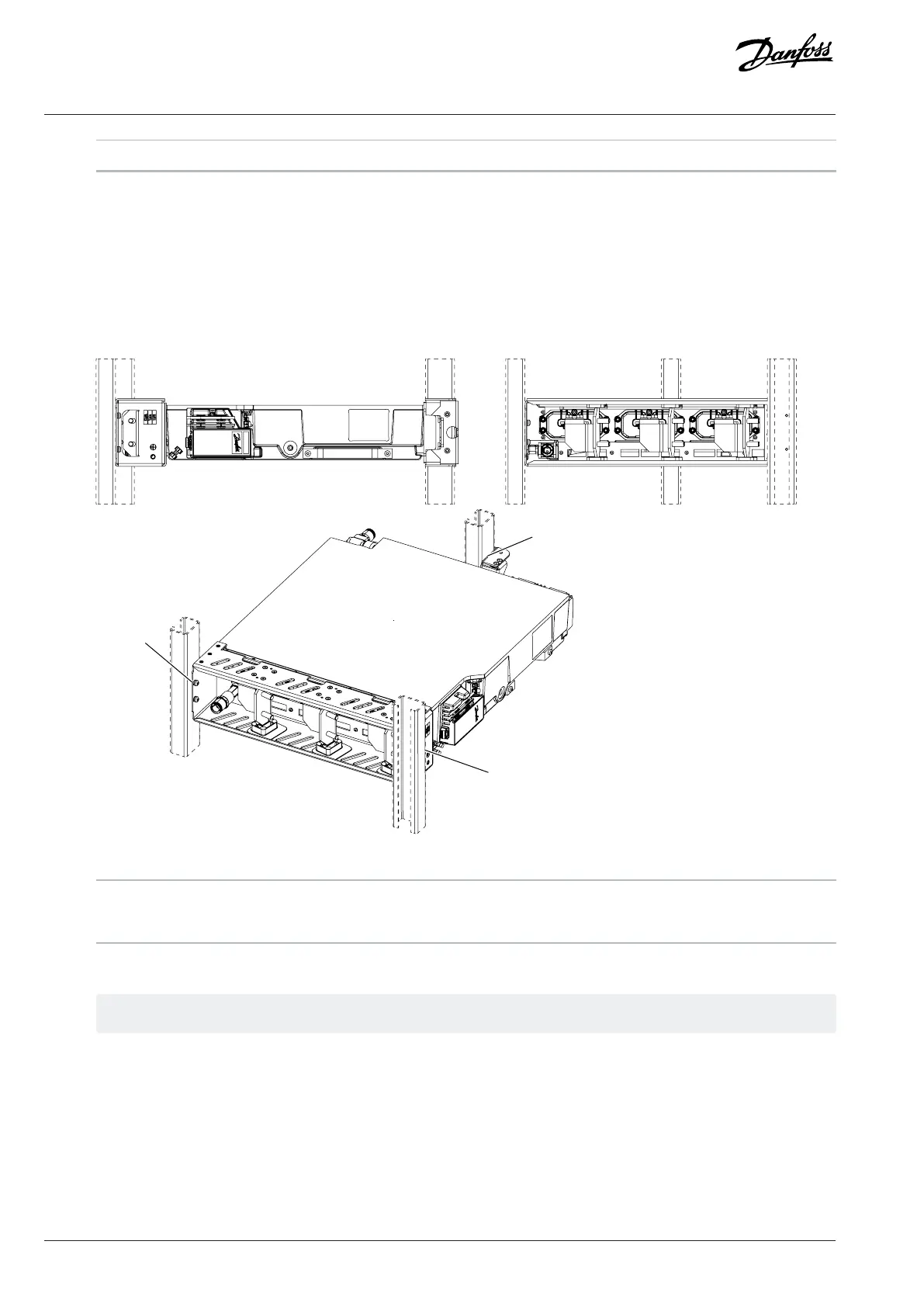
1. Install the system module into the cabinet in a horizontal position on its left side.
2. Use mounting holes to attach the system module into the cabinet.
a. Use M6 grade 8.8 screws.
b. For an AM12L or IM12L, use M8 grade 8.8 screws for the lower parts.
Figure 14: Mounting Holes of the System Module in Horizontal Position
1 Mounting holes 2 View from the front
3 View from the bottom
3. Attach the system module to the mounting brackets of the cabinet.
The mounting brackets are not included in the delivery.
5.3.3.3 Installing System Modules into a Cabinet on their Backsides
1. Install the system module into the cabinet on its backside.
2. Use mounting holes to attach the system module into the cabinet.
a. Use M6 grade 8.8 screws.
b. For an AM12L or IM12L, use M8 grade 8.8 screws for the lower parts.
30 | Danfoss Drives Oy © 2024.03 AJ475942178716en-000101 / 172K2848A
Design Guide | iC7 Series Liquid-cooled System Modules
 Loading...


