Design Guide | iC7 Series Liquid-cooled System Modules
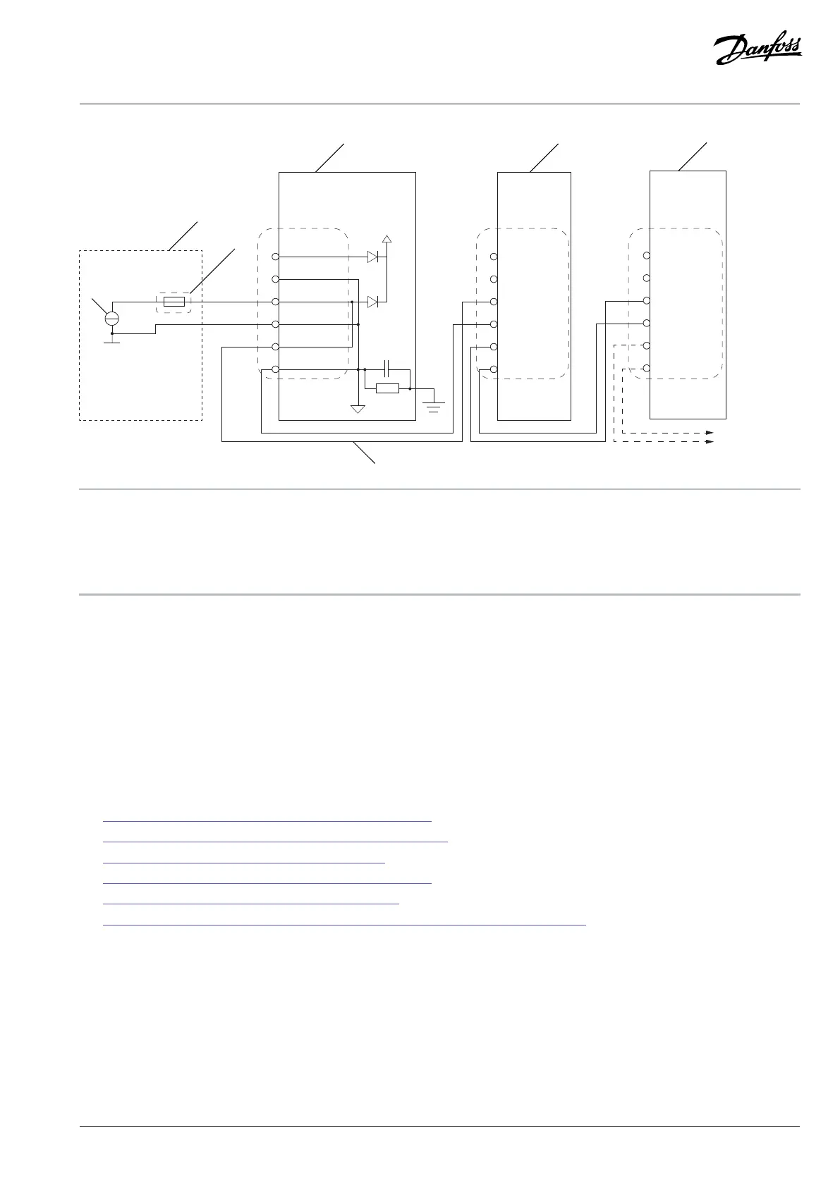
+24V input
GND
GND
GND
+24V output
+24V ext input
+24V input
GND
GND
GND
+24V output
+24V ext input
+24V input
GND
GND
GND
+24V output
+24V ext input
A Normal external supply B Reference design, daisy-chained +24 V power
C Fuse (Fuse rating depends on the complete daisychained
system configuration. Maximum 10 A.)
D Control board
E Power daisy-chaining
Figure 169: Wiring Diagram of a Daisy-chained +24 V Supply for the Control Units
10.4 Cable Sizes
10.4.1 List of Cable Size Information
The cable sizing is based on the ambient temperature of 40 °C (104 °F), cables laid side by side on cable ladders, maximum 9 cables
per ladder, and 3 ladders on top of each other. Use cable insulation that can withstand a temperature of at least 90 °C (194 °F). In other
conditions, refer to the local safety regulations, the input voltage, and the load current of the drive.
The cable size tables for the liquid-cooled system modules can be found with these links.
l 10.4.2 Field Cable Sizes for AFE and GC Modules, 525–690 V AC
l 10.4.3 Internal Cable Sizes for AFE and GC Modules, 525–690 V AC
l 10.4.4 Field Cable Sizes for INU Module, 525–690 V AC
l 10.4.5 Marine Cable Sizes for AFE or GC Modules 525–690 V AC
l 10.4.7 Marine Cable Sizes for INU Modules 525–690 V AC
l 10.4.6 Source Cable Sizes for DC/DC Converter Modules, 640–1100 V DC and 640–1200 V DC
10.4.2 Field Cable Sizes for AFE and GC Modules, 525–690 V AC
The AFE and GC modules with integration units do not have field cabling terminals for mains. Connect the AFE and GC modules to
adequate size field cabling terminals or switching device.
Danfoss Drives Oy © 2024.03 AJ475942178716en-000101 / 172K2848A | 167
 Loading...


