Design Guide | iC7 Series Liquid-cooled System Modules
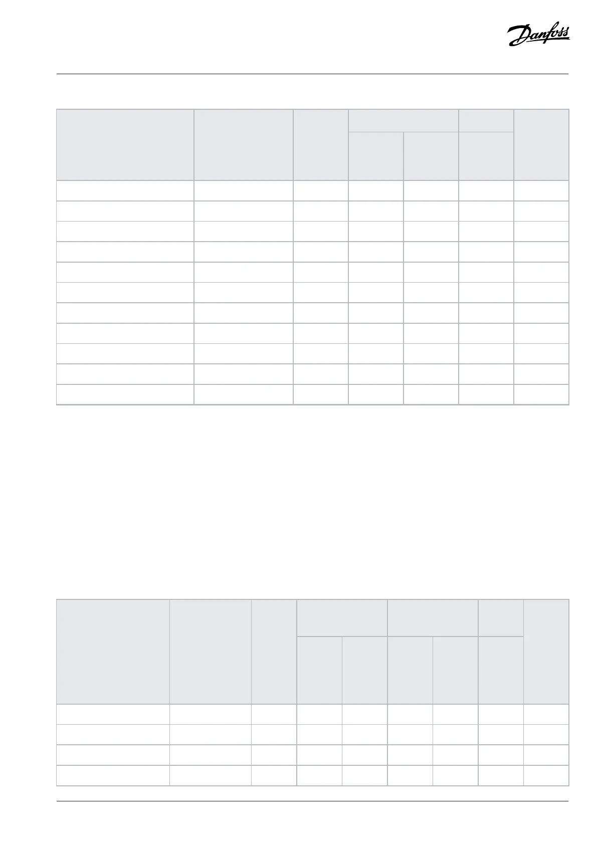
Table 69: Power Loss for AFE and GC Modules (continued)
System module
+AKFX
(1)(1)
Model code Frame Rated
current
I
L(1/5)
[A]
Power loss
to liquid
[kW]
Power loss
to air [kW]
Power loss
to air [kW]
Standby
loss [kW]
iC7-60SL3AB5-1040 2xAM12L 1040 9.97 0.10 0.04 0.14
iC7-60SL3AB5-1230 2xAM12L 1230 12.23 0.12 0.07 0.14
iC7-60SL3AB5-1325 2xAM12L 1325 13.44 0.14 0.1 0.14
iC7-60SL3AB5-1500 2xAM12L 1500 15.80 0.16 0.13 0.14
iC7-60SL3AB5-1700 3xAM12L 1700 16.58 0.17 0.11 0.22
iC7-60SL3AB5-1800 3xAM12L 1800 17.79 0.18 0.09 0.22
iC7-60SL3AB5-2000 3xAM12L 2000 20.31 0.21 0.14 0.22
iC7-60SL3AB5-2250 3xAM12L 2250 23.70 0.24 0.2 0.22
iC7-60SL3AB5-2500 4xAM12L 2500 24.95 0.25 0.17 0.29
iC7-60SL3AB5-2650 4xAM12L 2650 26.87 0.27 0.19 0.29
iC7-60SL3AB5-2940 4xAM12L 2940 30.76 0.31 0.28 0.29
1) DC fuses
10.7.5 Power Losses of AFE and GC Modules, Voltage Class B5, with +AEZ1 and +AEZ3
l The specifications for the values in the table
¢ AFE or GC module
¢ 380–500 V AC (465–800 V DC)
¢ DC voltage 594 V DC
¢ Modulator type 4
n The default modulator type for grid converters is type 5, which results in slightly lower losses than given in the table.
¢ Option +AEZ1 or +AEZ3
Table 70: Power Loss for AFE and GC Modules with Options +AEZ1 and +AEZ3
System module and
+AEZ1
(1)(1)
System module and
+AEZ3
(2)(2)
+AKFX
(3)(3)
Model code Frame Rated
current
I
L(1/5)
[A]
Power
loss to
liquid
[kW]
Power
loss to
air [kW]
Power
loss to
liquid
[kW]
Power
loss to
air [kW]
Power
loss to
air [kW]
Standby
loss,
system
module
and
+AEZ1
[kW]
iC7-60SL3AB5-261A AR10L 261 3.12 0.20 3.26 0.29 0.02 0.04
iC7-60SL3AB5-325A AR10L 325 4.22 0.25 4.43 0.38 0.02 0.04
iC7-60SL3AB5-380A AR10L 380 5.33 0.32 5.62 0.51 0.03 0.04
iC7-60SL3AB5-425A AR12L 425 4.47 0.19 4.58 0.26 0.01 0.07
Danfoss Drives Oy © 2024.03 AJ475942178716en-000101 / 172K2848A | 197
 Loading...


