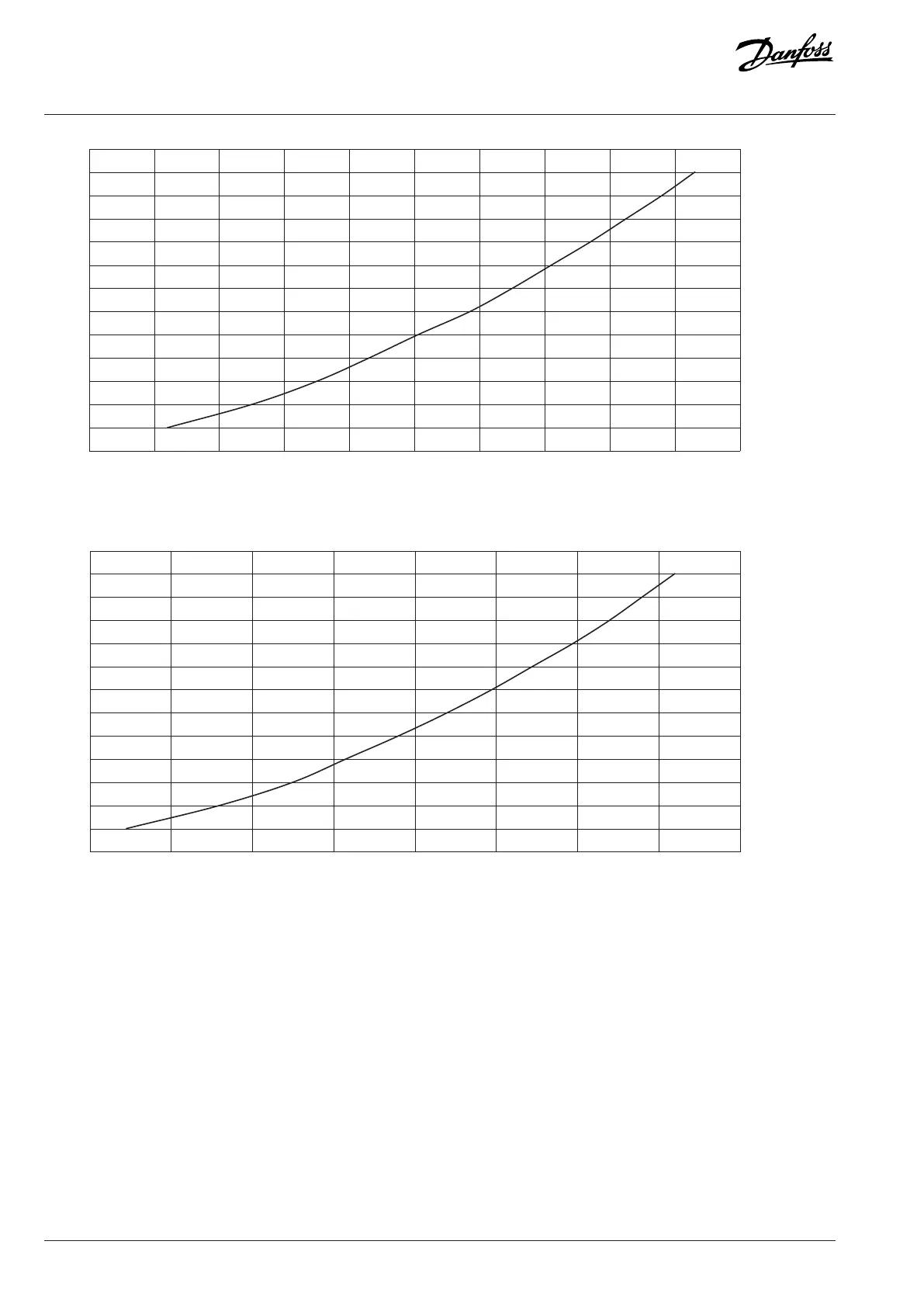
Figure 44: Pressure Drop with Water, DC Filter for DC/DC Converter OF7D1, 570 A
Figure 45: Pressure Drop with Water, DC Filter for DC/DC Converter OF7D1, 1200 A
6.4.6 Cooling Circuit Connectors
The cooling system has cooling circuit connectors located in the manifold plate. The internal thread size of the cooling circuit connectors
is G1/2. The depth of the threads is 13 mm (0.5 in). The maximum tightening torque is 30 Nm (266 in-lb). The push-in connectors are
available as an option.
The inlet connectors are at the bottom of the system module. The outlet connectors can be at the top or at the bottom.
If the optional outlet connectors at the top are used, the outlet connectors at the bottom must be closed with a plug.
52 | Danfoss Drives Oy © 2024.03 AJ475942178716en-000101 / 172K2848A
Design Guide | iC7 Series Liquid-cooled System Modules
 Loading...


