Design Guide | iC7 Series Liquid-cooled System Modules
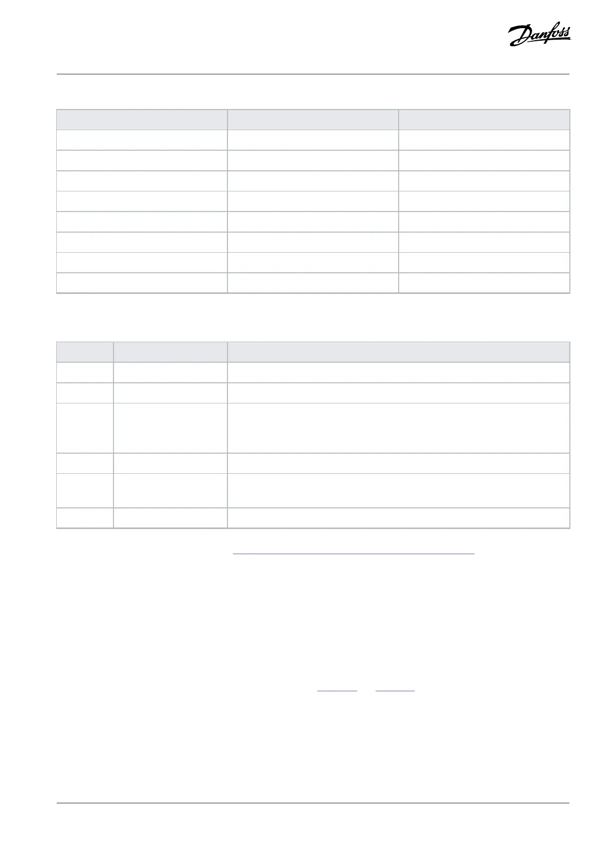
Table 23: STO Terminal Signals (X33) for the Inverter Module (continued)
Terminal Function Description
42 S.INA+ + Safe Input Channel A
43 S.INB+ + Safe Input Channel B
44 S.FB+ + STO Feedback
45A
(1)
GND 0 V/GND
45B
(1)
GND 0 V/GND
46 S.INA- - Safe Input Channel A
47 S.INB- - Safe Input Channel B
48 S.FB- - STO Feedback
1) Terminals 41A, 41B, 45A, and 45B have double pins to make connections easier.
Table 24: 24 V DC Supply Signals (X62)
Terminal Function Description
101 +24 V input Internal +24 V DC, 60 W control supply
102 GND Power supply ground
61 +24 V external input External +24 V DC control supply, maximum 10 A.
Must be fuse-protected.
Possible to daisy chain for multiple controllers.
62 GND Power supply ground
63 +24 V output +24 V DC output for daisy chain, only available when the +24 V DC external input con-
trol supply is used.
64 GND Power supply ground
For the circuit diagrams of the control unit, see 10.3.11 Wiring Diagrams of the +24 V Supply for the Control Unit.
8.5 Star Coupler Board
System modules for high current ratings consist of multiple power units that are connected via a star coupler board to 1 control unit.
With the star coupler board, it is possible to connect up to 16 power units in parallel. The fiber connection is always needed between the
control board and star coupler board.
An external 24 V power supply is required for the star coupler board. Connect the supply to the top of the star coupler board.
The star coupler board can be installed next to the control unit. The star coupler board can also be installed near the power units to make
the cabling from the star coupler board to the power units easier. See Figure 101 and Figure 102.
Danfoss Drives Oy © 2024.03 AJ475942178716en-000101 / 172K2848A | 97
 Loading...


