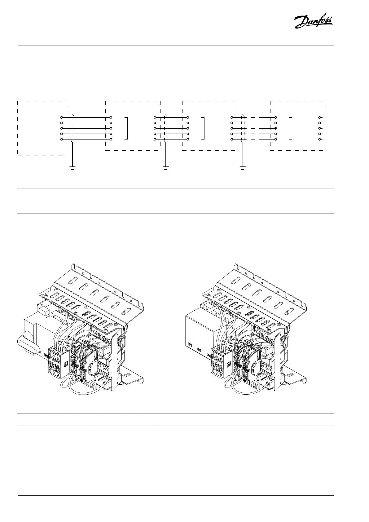
7.14.3 AuxBus Grounding Principles
To ensure robust communication, good grounding strategy is needed. Below is a recommended grounding strategy illustrated using
integration units. Same strategy can be applied for loose option filters.
+24 V
2
GND
3
CAN_H
4
CAN_L
5
+24 V
+24 V
2
GND
3
CAN_H
4
CAN_L
5
+24 V
5
Term. Disable
5
Term. Disable
e30bh675.10
Figure 90: AuxBus Circuit Diagram
A The AuxBus interface in the power unit B AuxBus board 1
C AuxBus board 2 D AuxBus board 3
7.15 The Pre-charging Unit
The pre-charging unit is used for pre-charging the system modules that are connected to the same DC bus. There are 3 electrical sizes,
and an IEC and an UL variant of these. The pre-charging unit is available as an accessory.
Figure 91: Pre-charging Units
1 Pre-charging unit, IEC 2 Pre-charging unit, UL
88 | Danfoss Drives Oy © 2024.03 AJ475942178716en-000101 / 172K2848A
Design Guide | iC7 Series Liquid-cooled System Modules
 Loading...


