Design Guide | iC7 Series Liquid-cooled System Modules
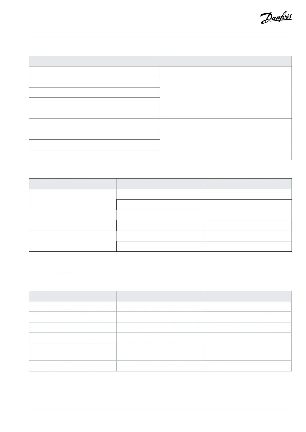
Table 17: Selection of the Correct Pre-charging Unit
System modules Pre-charging unit
IM10L + IM10L / IR10L + IR10L
IM12L + IM12L / IR12L + IR12L
2 x IM12L + 2 x IM12L / 2 x IR12L + 2 x IR12L
3 x IM12L + 3 x IM12L / 3 x IR12L + 3 x IR12L
4 x IM12L + 4 x IM12L / 4 x IR12L + 4 x IR12L
Pre-charging unit 10 (IEC or UL)
5 x IM12L + 5 x IM12L / 5 x IR12L + 5 x IR12L
6 x IM12L + 6 x IM12L / 6 x IR12L + 6 x IR12L
7 x IM12L + 7 x IM12L / 7 x IR12L + 7 x IR12L
8 x IM12L + 8 x IM12L / 8 x IR12L + 8 x IR12L
Pre-charging unit 20 (IEC or UL)
Table 18: Maximum Capacitance of the Pre-charging Unit
Pre-charging unit Network [V AC] Capacitance [µF]
400/500 66500Pre-charging unit 10 (IEC or UL)
690 29500
400/500 184000Pre-charging unit 20 (IEC or UL)
690 76500
400/500 275000Pre-charging unit 30 (IEC or UL)
690 114500
There are thermal restrictions in a repeated use of the pre-charging unit. See the allowed pre-charging cycle in a 60 °C (140 °F) ambient
temperature in Table 19.
Table 19: The Thermally Allowed Pre-charging Cycle
Step Task Duration
1. Charging 10 s
2. Discharging 50 s
3. Charging 10 s
4. Discharging 50 s
5. Wait for the pre-charging unit to cool
down.
10 min
6. Repeat –
Danfoss Drives Oy © 2024.03 AJ475942178716en-000101 / 172K2848A | 89
 Loading...


