EasyManuals Logo

Danfoss iC7 Series Design Guide

Danfoss iC7 Series
224 pages
To Next Page IconTo Next Page
To Previous Page IconTo Previous Page
Page #29 background imageLoading...
Page #29 background image
Design Guide | iC7 Series Liquid-cooled System Modules
b. For an AM12L or IM12L, use M8 grade 8.8 screws for the lower parts.
e30bh576.11
1
1
1
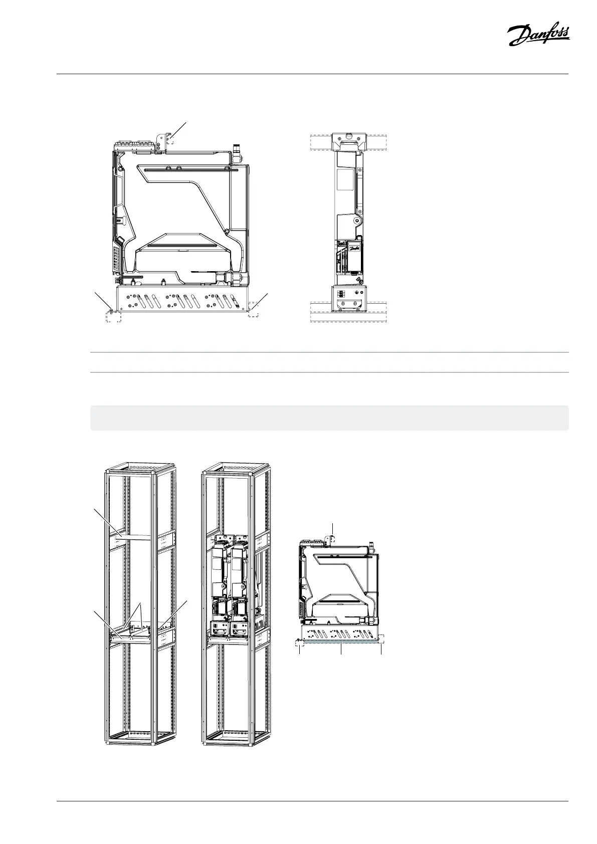
Figure 12: Mounting Holes of the System Module in Vertical Position
1 Mounting holes
3. Attach the system module to the mounting brackets of the cabinet.
The mounting brackets are not included in the delivery.
a. To ease the removal of the system module from the cabinet for service, use support bars under the system module.
e30bh511.12
1
1
1
21 1
1
2
Figure 13: The Mounting Brackets and the Installation of System Modules into the Cabinet
Danfoss Drives Oy © 2024.03 AJ475942178716en-000101 / 172K2848A | 29

Table of Contents

Other manuals for Danfoss iC7 Series

Questions and Answers:

Question and Answer IconNeed help?

Do you have a question about the Danfoss iC7 Series and is the answer not in the manual?

Danfoss iC7 Series Specifications

General IconGeneral
Product TypeMedia Converter
Power Supply24 VDC
Housing MaterialPlastic
MountingDIN Rail
ManufacturerDanfoss
Protection ClassIP20
Protocols SupportedModbus
Humidity5% to 95% (non-condensing)
Weight150 g
SeriesiC7 Series

Related product manuals