Design Guide | iC7 Series Liquid-cooled System Modules
l Container large enough for the drained coolant. One system module can hold 0.55 l of coolant.
l To perform the procedure easily, 2 people are required.
l Pressurized air can be used for the draining. Maximum pressure is 5 bar.
1. Remove the power unit from the integration unit.
2. Place the power unit in a vertical position and place the container below the coolant inlet at the bottom of the module.
3. To open the quick-release connectors of the coolant outlet and inlet, push in the valves with a blunt tool.
Do not insert sharp or hard metallic objects in the connectors. Sharp objects can damage the connectors or the sealing
inside the connectors.
4. Drain the coolant to the container. To drain all the coolant:
– Tilt the module, or
– Supply pressurized air to the outlet connector.
5. Dispose of the coolant according to local laws and regulations.
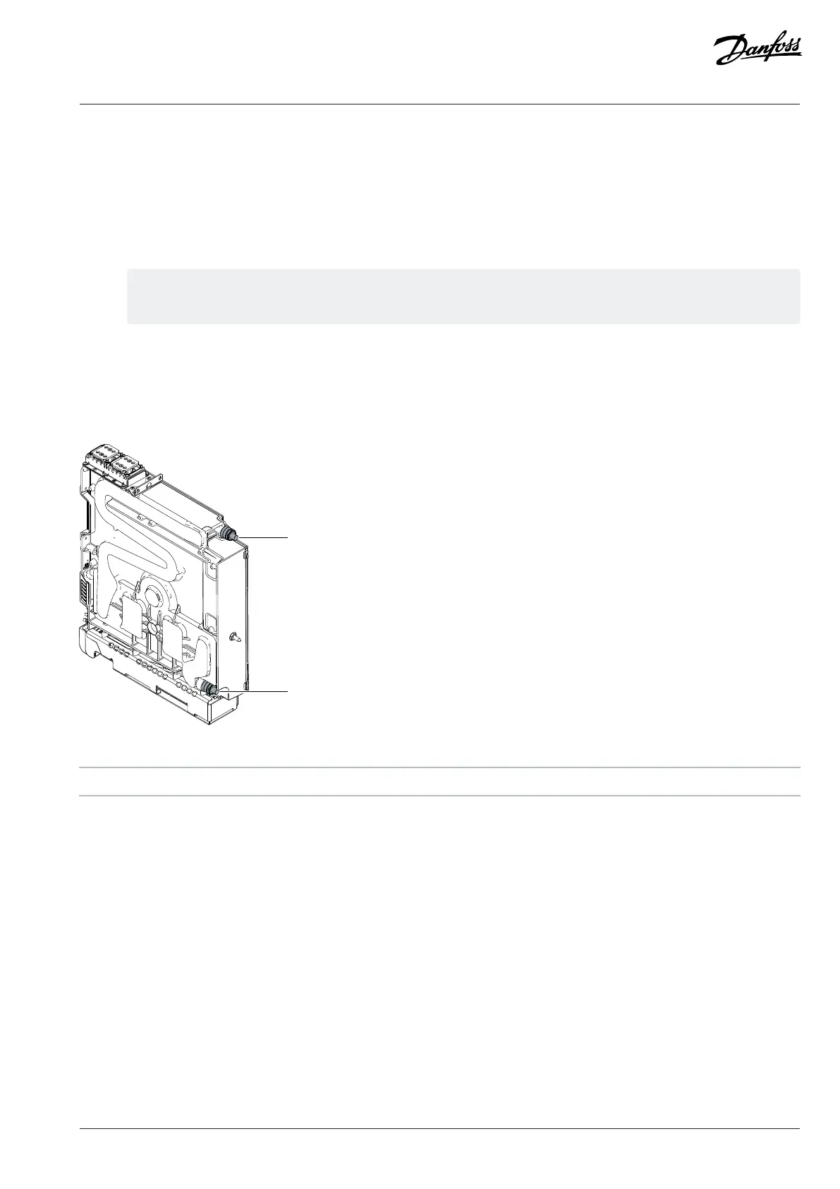
Figure 126: Inlet and Outlet Connectors of Power Units for xR10L and xR12L
1 Outlet connector 2 Inlet connector
Danfoss Drives Oy © 2024.03 AJ475942178716en-000101 / 172K2848A | 125
 Loading...


