7. Close all the valves in cabinets C1 and C2 except for the valves V5, V6, V7, and V8 of the first system module (M1).
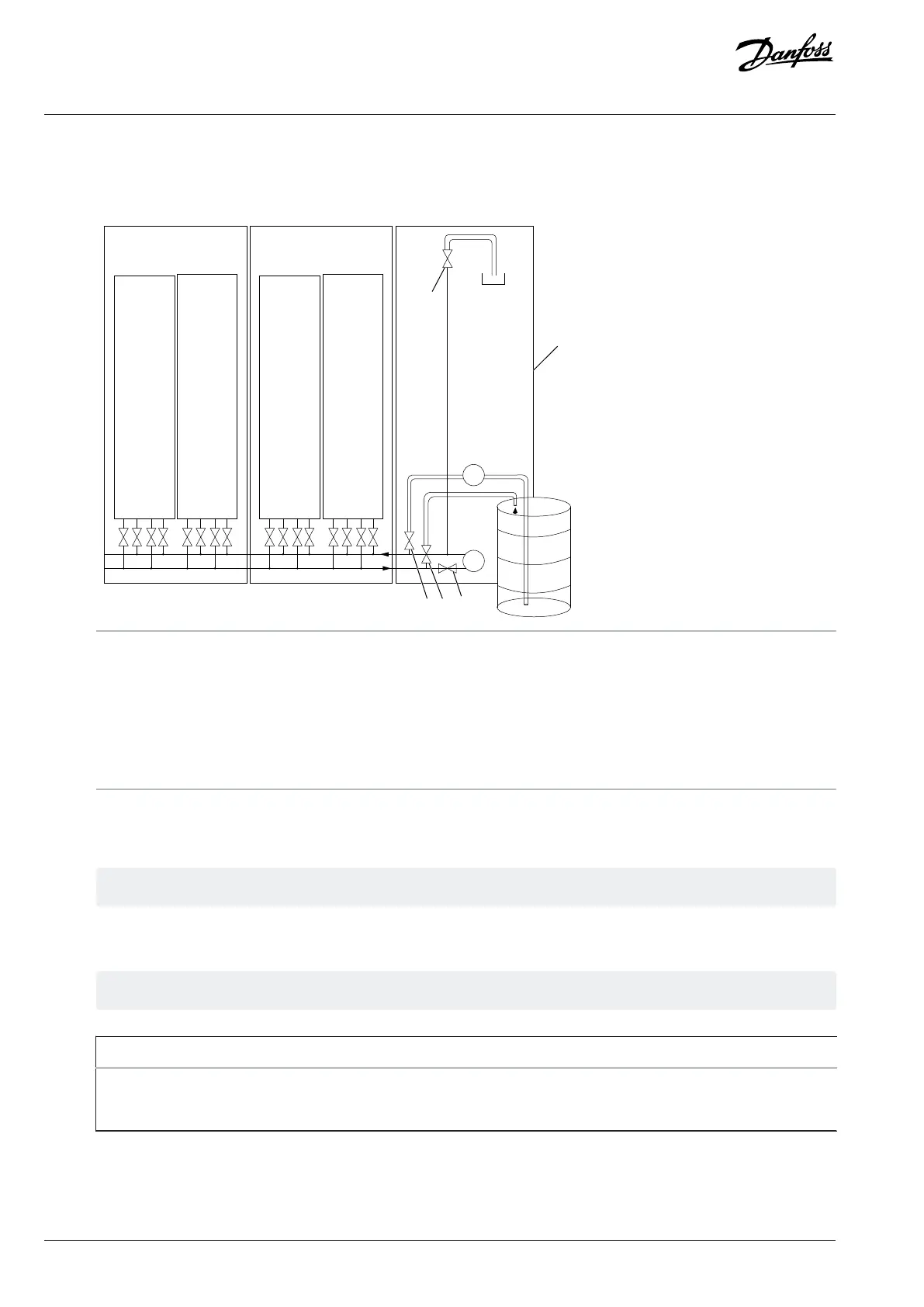
Figure 53: Example of Filling the Cooling System with Liquid
1 Cooling module A Filling valve
B Draining valve C Pump shut-off valve
C1 First cabinet C2 Second cabinet
D De-airing valve P
f
Filling pump
P Pump, cooling module
8. Open the valves A (V212) and B (V213) of the cooling module.
9. If you have a Danfoss cooling module, make sure that the valve V211 is open.
The valve V211 is in series with V212.
10. Start the filling pump P
f
.
11. Wait for the system module M1 to fill up.
See the table for examples of filling times.
Flow rate Time [minutes]
10 l/min 10
15 l/min 1
60 | Danfoss Drives Oy © 2024.03 AJ475942178716en-000101 / 172K2848A
Design Guide | iC7 Series Liquid-cooled System Modules
 Loading...


