User Interface
84
DX8210 Barcode Scanner
Examples: Logical Combination Rule
For all the following examples the No Read Message parameter is set to Global No
Read Message.
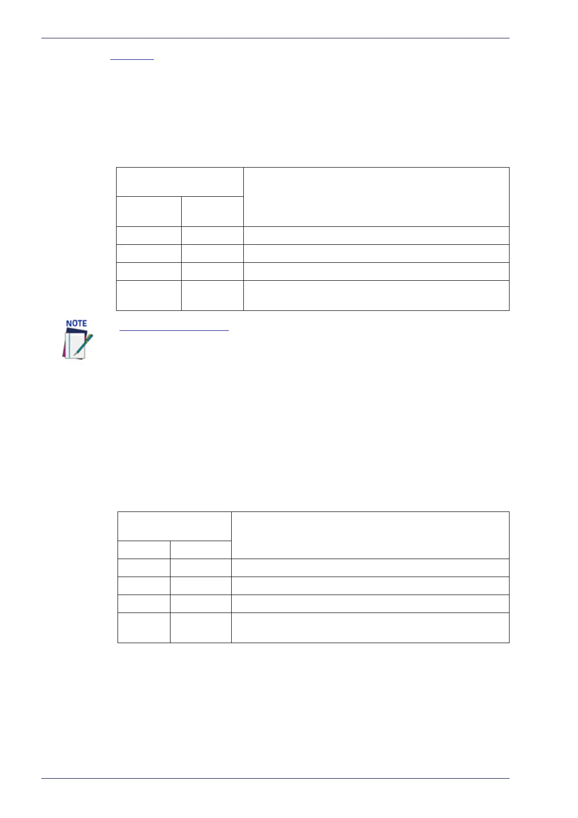
Example 1
Code label setting#1 = Code 128
Logical Combination Rule = 1&1
Defines 2 groups, each of them expecting a Code 128 label.
Example 2
Code label setting#1 = Code 39
Code label setting#2 = Code 128
Logical Combination Rule = 1^2
Defines a single group expecting a Code 128 label OR a Code 39 label.
Example 3
Code label setting#1 = EAN 8
Code label setting#2 = UPC-A
Logical Combination Rule = 1&1&1^2
Defines three different groups. The first two groups expect an EAN 8 label while the
third one expects an EAN 8 label OR an UPC-A label.
Decoded Code
Symbology
Output Message
First Label
#1
Second
Label #1
--- --- <Header><Global No Read Message><Terminator>
X --- <Header><Global No Read Message><Terminator>
--- X <Header><Global No Read Message><Terminator>
XX
<Header><Code 128 data><Data Packet Separator><Code
128 data><Terminator>
If Multiple Read Message is enabled and a third label belonging to the Code 128 sym-
bology is decoded, the Multiple Read string is transmitted instead. If the Multiple Read
Message is disabled, the third code label is ignored and only the first two codes are
transmitted.
For advanced formatting, if the Send All Multiple Read Labels parameter is enabled,
then all three labels are sent in the output message; the multiple read label is sepa-
rated by its own Multiple Read Label Separator String which should be different from
the Data Packet Separator (DPS).
Decoded Code
Symbology
Output Message
Label #1 Label #2
--- --- <Header><Global No Read Message><Terminator>
X --- <Header><Code 39 data><Terminator>
--- X <Header><Code 128 data><Terminator>
XX
<Header><First decoded code/Multiple Read Message string
><Terminator>