Barcode Scanning Features
216
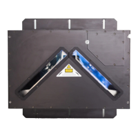
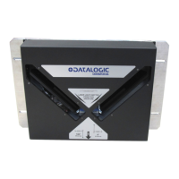
DX8210 Barcode Scanner
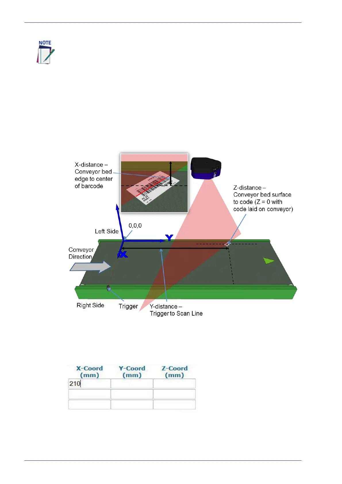
Top-Mounted Barcode Scanner Calibration Using PackTrack
With the belt stopped, measure and enter the barcode XYZ coordinate data for
each scanner as follows:
1. Make sure that the intended scanner (in a multi-head system) and Le
g1
have been selected from the drop-down lists at the top of the wizard win-
dow.
2. Lay a system barcode on the conveyor bed in the laser line close to the left
edge (X=
0 edge) of the conveyor bed. See illustration below.
3. Measure the distance for X from the edge of the conveyor bed to the center
of the barcode, and enter that distance in the first box under X-Coord (mm)
in the PackTrack Calibration Wizard. Your measurements will likely differ
from those shown below.
4. Measure the distance for Y from the trigger (PS line) to the barcode scan-
ner's laser line on the barcode, and enter that distance in the first box
un
der Y-Coord (mm).
It is not possible to illustrate every possible installation angle and scanner mounting
position in this manual. Use the following steps as a general guide to calibrating each
system scanner using barcodes in three positions. You will need to make adjustments
to the label/box position based on your situation. It is, however, important to note the
fixed XYZ coordinates of the conveyor.