Chapter 8 Option CardsMH300
8-8
8-1-3 Communication Card - Mounting position 1
Installation method: Back-mounting the option card, by inserting to a flat Cables on the control board.
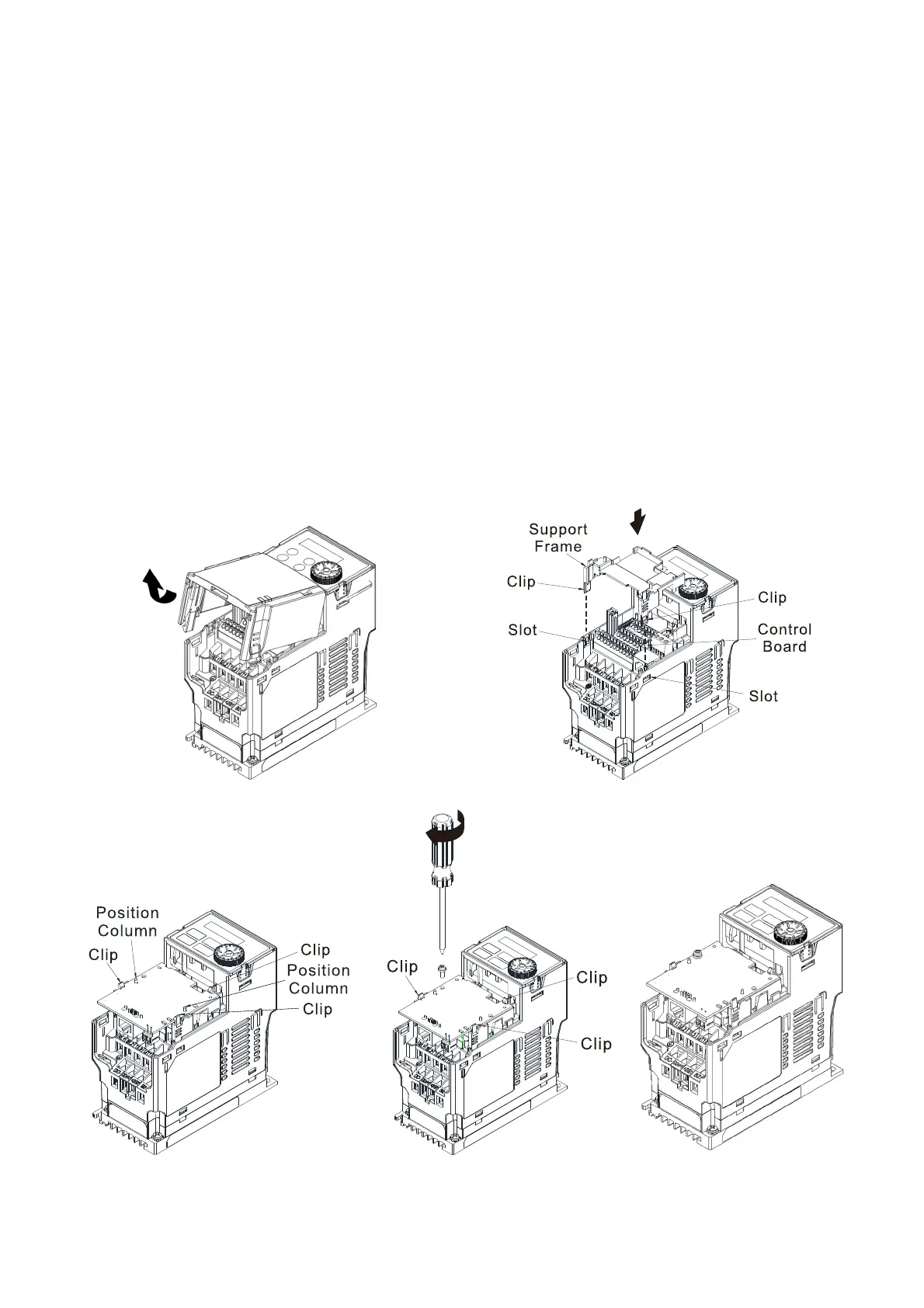
1. As shown in the Figure 8-21, shut down the power of the motor drive, and then remove the front cover.
2. Assembling connection cables: Connect the connector at one end of the connection cable to the
control board connector. For information on connection method, refer to Section 8-1 (see Table 8-2
and Figure 8-3).
3. Assembling support frame: as shown in the Figure 8-22, aim the two clips at the two slots on the motor
drive and then press downward to have the two clips engage the slots.
4. Assembling connection cables: Connect the connector at the other end of the connection cable to the
connector of communication cards.
5. Assembling the option card: As shown in the Figure 8-23, have the terminal block of the adapter/
option facing up, aim the two holes of the option card to the position column and press downward so
that the three clips are engage the option card.
6. As shown in the Figure 8-24, make sure that three clips are properly engage the adapter/ option card
and then fasten the screw [Suggested torque value: 4–6 kg-cm / (3.5–5.2 lb-in.) / (0.39–0.59 Nm)].
7. As shown in the Figure 8-25, assembly is completed.
Figure 8-21
Figure 8-22
Figure 8-23 Figure 8-24
Figure 8-25

 Loading...


