Chapter 8 Option CardsMH300
8-22
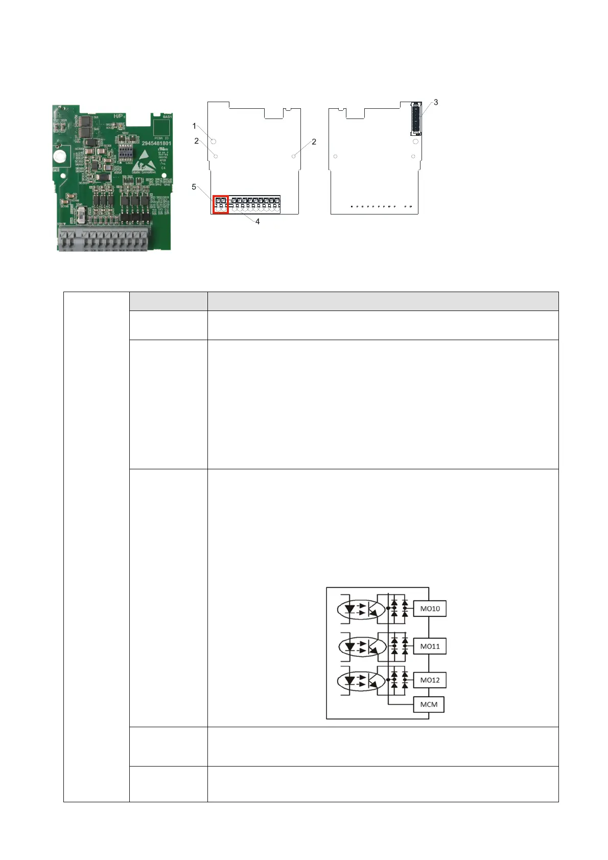
8-5 EMM-D33A -- Extension for 3-point Digital Input / 3-point Digital Output
8-5-1 Product Profile
Figure 8-61
Figure 8-62
Wire: 0.25–0.75 mm
2
/ (24–18 AWG)
Stripping length: 9 mm
1. Screw fixing hole
2. Positioning hole
3. AC motor drive
connection port
4. T
erminal block
5.
Ground terminal
block
Digital I/O
Extension
Card
Terminals Descriptions
24V, DCM Output power: +24 V
DC
±5% < 30mA
MI10––MI12
Refer to Pr.02-26–Pr.02-28 to program the multi-function.
Choose SINK (NPN) / SOURCE (PNP) by SWW1.
Internal power is supplied by terminal 24 V: +24V
DC
±5 %
If external power is +24 V
DC
, the maximum voltage is 30 V
DC
and the
minimum voltage is 19 V
DC
.
ON: the activation current is 6.5 mA.
OFF: leakage current tolerance is 10 μA.
MO10–MO12
Refer to Pr.02-36–Pr.02-38 to program the multi-function.
The motor drive outputs various monitor signals, such as drive in
operation, frequency reached and overload indication, through the
transistor (open collector).
MO output signal: each MO terminal needs a pull-up resistor, the
maximum external power voltage is 48 V
DC
/ 50 mA.
MCM
Common for multi-function output terminals MO10–MO12 (photo
coupler)
PE
Grounding terminal. To decrease noise, properly ground this
terminal.
Table 8-10

 Loading...


