Chapter 6 Control TerminalsMH300
6-1 Control Terminal Specifications
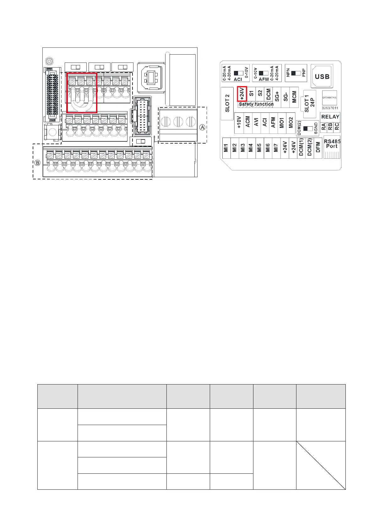
Fig. 6-6 Control Terminal Distribution Diagram
Fig. 6-7 Control Terminal Location Map
Wiring precautions:
The default condition is +24V / S1 / S2 shorted by jumper, as shown 1. in the Fig. 6-6. Refer to
Chapter 4 WIRING for more details
The +24V of safety function is for STO only, as shown 2. in the Fig. 6-7, and cannot be used for other
purpose.
The RELAY terminal uses the PCB terminal block (as shown area
○
A
in the Fig. 6-6):
1. Tighten the wiring with a 2.5 mm (wide) x 0.4 mm (thick) slotted screwdriver.
2. The ideal length of stripped wire at the connection side is 6–7 mm.
3. When wiring bare wires, make sure they are perfectly arranged to go through the wiring holes.
The Control terminal uses a spring clamp terminal block (as shown area
○
B
in the Fig. 6-6):
1. When removing wires, use the slotted screwdriver to press down the terminal, and the suggested
force is 1.5 kgf.
The specification of slotted screwdriver: 2.5 mm (wide) x 0.4 mm (thick).
2. The ideal length of stripped wire at the connection side is 9 mm.
3. When wiring bare wires, make sure they are perfectly arranged to go through the wiring holes.
Wir
ing Specifications of Control Terminal
Function
name
Conductor
Stripping
length (mm)
Maximum
wire gauge
Minimum
wire gauge
tightening
RELAY
Terminals
Conductor cross section
solid wire
6~7
1.5mm
2
(16AWG)
0.2 mm
2
(24AWG)
5 Kg-cm
(4.3 lb-in.)
(0.49 Nm)
Conductor cross section
stranded wire
Control
Terminals
Conductor cross section
solid wire
9
0.75mm
2
(18AWG)
0.2 mm
2
(24AWG)
Conductor cross section
stranded wire
Stranded with ferrules with
plastic sleeve
9

 Loading...


