Chapter 8 Option CardsMH300
8-19
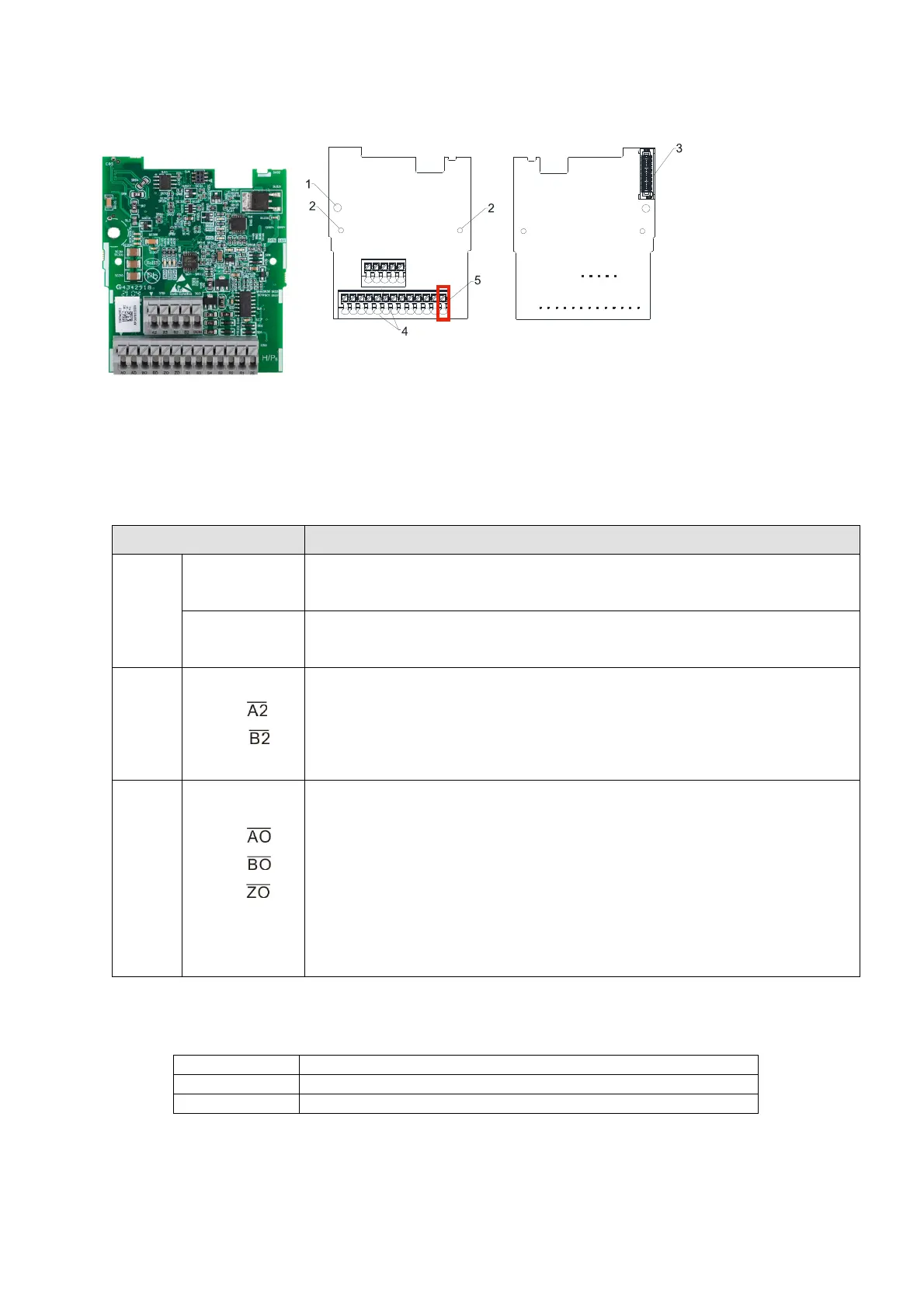
8-4 EMM-PG01R -- PG Card (Resolver / Encoder Signal Input)
8-4-1 Product Profile
Figure 8-57
Figure 8-58
Wire: 0.25–0.75 mm
2
/ (24–18 AWG)
Stripping length: 9 mm
1. Screw fixing hole
2. Positioning hole
3. AC motor drive
connection port
4. T
erminal block
5.
Ground terminal
block
8-4-2 T
erminal Descriptions
To use with Pr.10-00–Pr.10-02 and Pr.10-30. And Pr.10-30 is using for resolver pole pair.
(When using EMM-PG01R, set Pr
.10-00 = 3 and set Pr.10-01 = 1024.)
Terminals Descriptions
PG1
R1- R2
Resolver Output Power
7 Vrms, 10 kHz
S1, S3,
S2, S4
Resolver input signal (S2, S4
= Sin; S1,
S3
= Cos)
3.5 ± 0.175 Vrms, 10 kHz
PG2
A2, ,
B2,
Pulse input signal (Applicable for Line Driver or Open Collector)
Open Collector input voltage: +5–24V (see NOTE 1)
Support 1-phase and 2-phase input.
Maximum output frequency: 300 kHz
PG OUT
AO, ,
BO, ,
ZO, ,
DCM
PG Card output signal: supports frequency elimination: 1–255 times
Maximum output voltage of Line driver: 5 V
DC
Maximum output current: 50 mA
Maximum output frequency: 300 kHz
DCM, the referenced electric potential for PG card output signal, serves as the
ground for host controller or PLC to make the output signal become the
common point.
Table 8-8
NOTE:
1. Open
Collector application: Input current 5–15 mA to each set and each set needs one pull-up resistor.
5 V Recommended pull-up resistor above: 100–220 , 1/2 W
12 V Recommended pull-up resistor above: 510 –1.35 k, 1/2 W
24 V Recommended pull-up resistor above: 1.8 k–3.3 k, 1/2 W
Table 8-9

 Loading...


