Chapter 8 Option CardsMH300
8-20
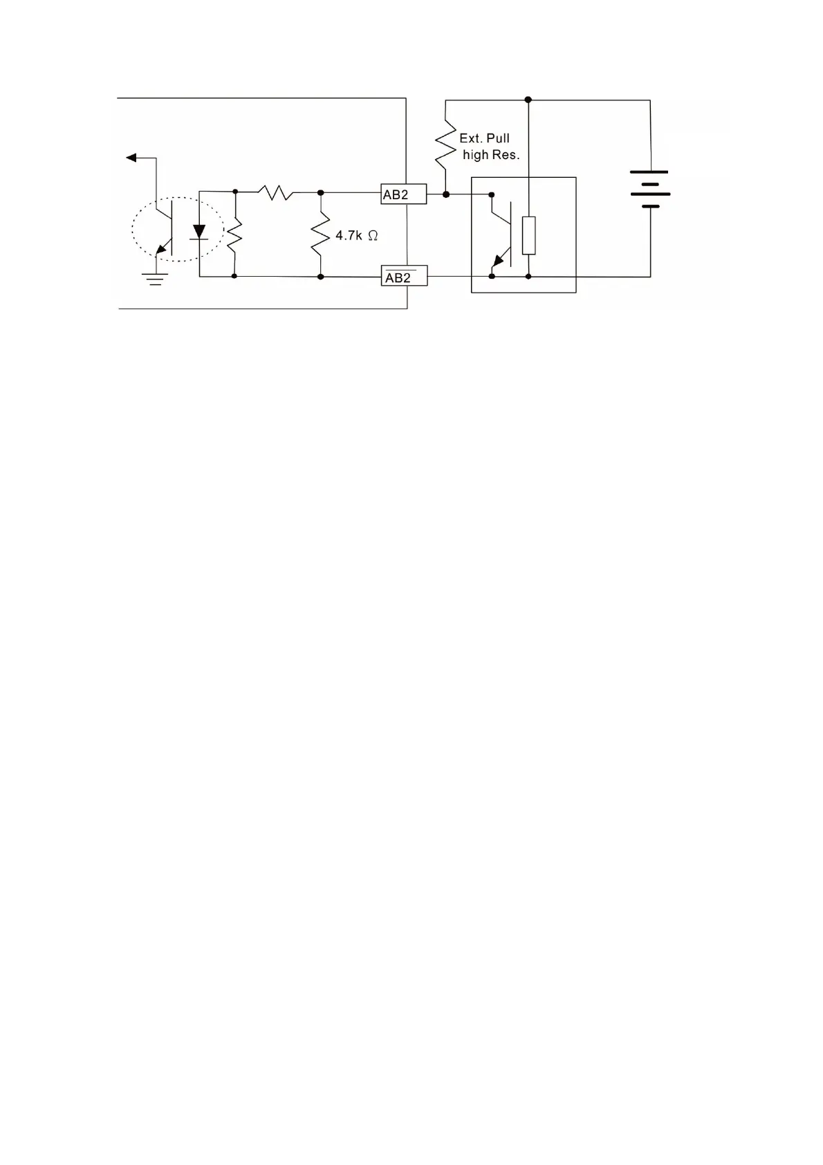
PG2 Wiring Diagram
Figure 8-59
2. DOS (Degradation of Signal):
If the amplitude of the sine wave input of the S1- / S3 and S2- / S4 is lower than or higher than the
encoder IC’s specification, a red light turns on. The possible reasons for this problem are:
a. The turns ratio of the resolver encoder is not 1:0.5, which makes the sine wave input of the S1- /
S3 and S2- / S4 be not equal to 3.5 ± 0.175 Vrms.
b. While the motor is running, the motor creates common mode noise that makes the accumulated
voltage greater than 3.5 ± 0.175 Vrms.
3. LOT (Loss of Tracking):
Compare the angle of the S1- / S3 and S2- / S4 sine wave input to the R1-R2 cosine wave. If their
difference is more than 5 degrees, a red light turns on. The possible reasons for this problem are:
a. The output frequency of the PG card is incorrect.
b. The specification of Resolver’s encoder is not 10 kHz.
c. The motor creates common mode noise while it is running. While the motor is rotating, it
causes a big difference between the main winding’s cosine wave angle and the sine wave
angle of the second and third windings.
Ext. Power
5
24V

 Loading...


