Chapter 16 PLC Function ApplicationsMH300
16-4 Basic Principles of PLC Ladder Diagrams
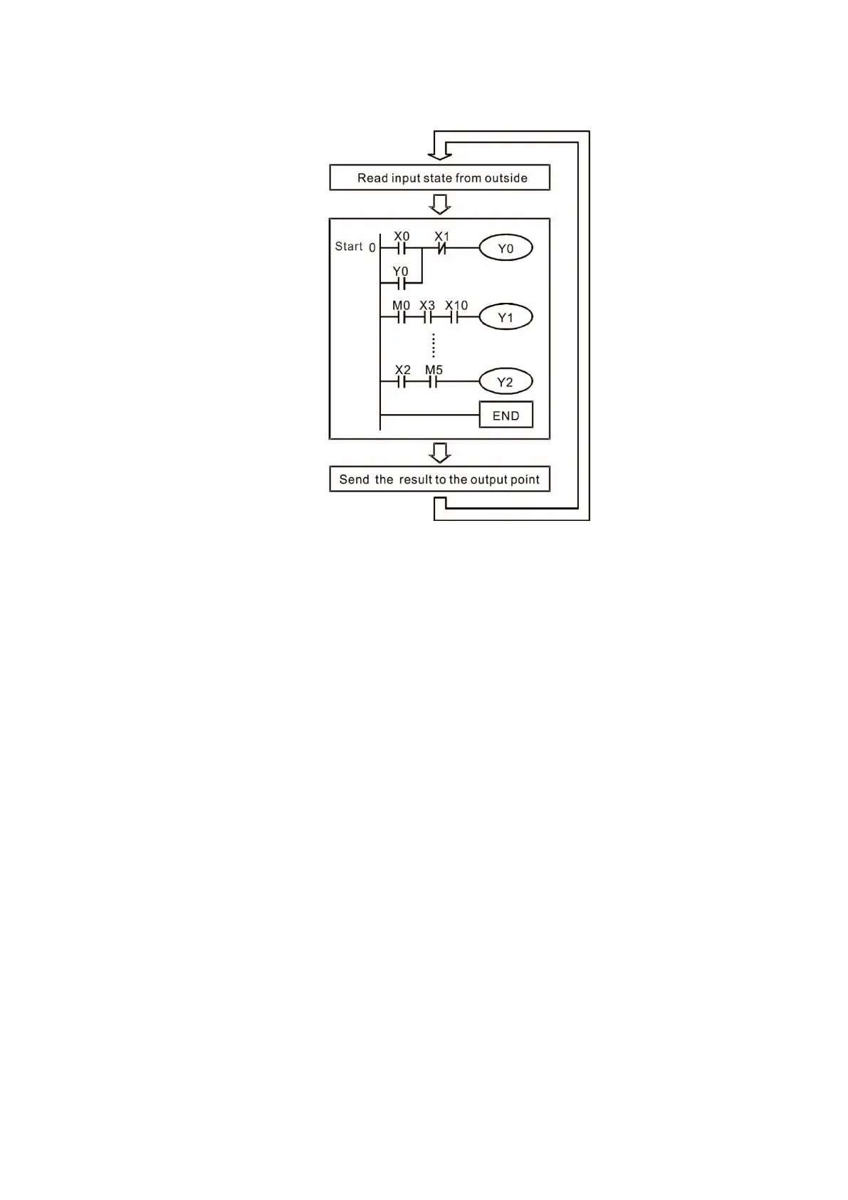
16-4-1 Schematic diagram for PLC ladder diagram program scanning
Output r
esults are calculated on
the basis of the ladder diagram
configuration
(internal devices have real-time
output before results are sent to
an external output point)
Figure 16-27
Repeated
program scans
16-4-2 Introduction to ladder diagrams
Ladder di
agrams use a graphic language widely applied in automatic controls. They employ
common electrical control circuit symbols. After you use a ladder diagram editor to create a ladder
diagram program, the PLC program design is complete. Using a graphic format to control processes
is very intuitive and is readily accepted by personnel who are familiar with electrical control circuit
technology. Many of the basic symbols and actions in a ladder diagram mimic common electrical
devices in conventional automatic control power distribution panels, such as buttons, switches, relays,
timers, and counters.
Internal PLC devices: The types and quantities of internal PLC devices vary in different brands of
products. Although these internal devices use the same names as the conventional electrical control
circuit elements (such as relays, coils, and contacts), a PLC does not actually contain these physical
devices, and they instead correspond to basic elements in the PLC’s internal memory (bits). For
instance, if a bit is 1, this may indicate that a coil is electrified; and if that bit is 0, it indicates that the
coil is not electrified. You can use a N.O. contact (Normally Open, or contact A) to directly read the
value of the corresponding bit, and use a N.C. contact (Normally Closed, or contact B) to get the
inverse of the bit’s value. Multiple relays occupy multiple bits, and eight bits comprise one byte. Two
bytes comprise one word, and two words comprise a double word. When multiple relays are
processing at the same time (as in addition/subtraction or displacement), it can use a byte, a word, or
a double word. Furthermore, a PLC contains two types of internal devices: a timer and a counter. It
not only has a coil, but can count time and numerical values. Because of this, when it is necessary to
process numerical values, these values are usually in the form of bytes, words, or double words
(internally in the PLC).

 Loading...


