Chapter 6 Control TerminalsMH300
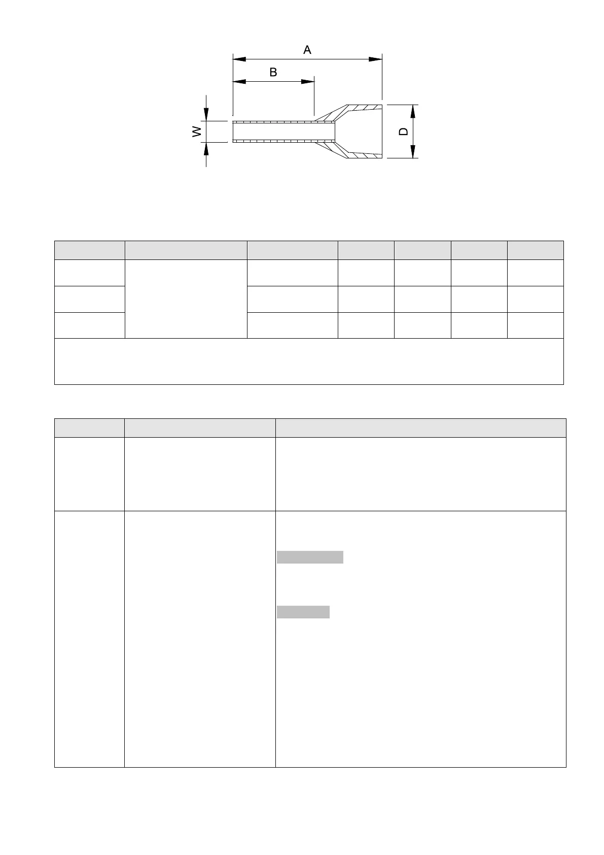
Fig. 6-8
Recommended model and size of crimp terminals Unit: mm
AWG Vendor Vendor P/N A(MAX) B(MAX) D(MAX) W(MAX)
PHOENIX CONTACT
AI 0,25- 8 YE 12.5 8 2.6 1.1
AI 0,34- 8 TQ 12.5 8 3.3 1.3
AI 0,5 - 8 WH 14 8 3.5 1.4
Recommended model and specifications of crimp tool:
CRIMPFOX 10S - 1212045, Manufacturer: PHOENIX CONTACT
DNT13-0101, Manufacturer: DINKLE
Terminals Terminal Function Description
+24 V
Digital control signal common
(Source)
+24 V ± 10% 100 mA
When used in parallel, if the +24V terminal is used with a
feedback sensor, unequal current may occur, and there
will be a risk of failure.
MI1–MI7 Multi-function input 1–7
Refer to Pr.02-01–02-07 to program the multi-function
inputs MI1–MI7.
Source mode
ON: the activation current is 3.3 mA ≥
11 V
DC
OFF: cut-off voltage ≤
5 V
DC
Sink mode
ON: the activation current is 3.3 mA ≤
13 V
DC
OFF: cut-off voltage ≥
19 V
DC
When Pr.02-00 = 0, MI1 and MI2 can be programmed.
When Pr.02-00
≠
0, the function of MI1 and MI2 is
according to Pr.02-00 setting.
When Pr.02-07 = 0, MI7 is pulse input terminal
MI7 uses pulse input, the maximum input frequency =
33 kHz.

 Loading...


