Chapter 6 Control TerminalsMH300
Terminals Terminal Function Description
DFM
Digital frequency meter
DFM is a pulse-signal output; Duty-cycle: 50%
Minimum load impedance R
L
: 1 kΩ / 100 pf
Maximum current: 30 mA
Maximum voltage: 30 V
DC
± 1%
(when 30 V
DC
/ 30 mA / R
L
= 100 pf)
Maximum output frequency: 33 kHz
Internal current limiting resistor R: ≥
1 KΩ
Output load impedance R
L
Capacitive load ≤ 100 pf
Resistive load ≥1 kΩ resistance determines the output
voltage value.
DFM-DCM voltage = external voltage * ( R
L
/ (R
L
+R) )
DCM
(1)
Digital frequency signal
common (Sink)
DCM
(2)
Digital frequency signal
common (Sink), it can switch
to SGND
MO1
Multi-
coupler)
The AC motor drive output various monitoring signals,
such as drive in operation, frequency reached, and
overload indication through a transistor (open collector).
Max 48
DC
50 mA
MO2
Multi-
coupler)
MCM
Multi-function Output
Common
RA
Multi-function relay output 1
(Relay N.O. a)
Resistive load
3 A (N.O.) / 3 A (N.C.) 250
V
AC
5 A (N.O.) / 3 A (N.C.) 30
V
DC
Inductive load (COS 0.4)
1.2 A (N.O.) / 1.2 A (N.C.) 250
V
AC
2.0 A (N.O.) / 1.2 A (N.C.) 30
V
DC
Various kinds of monitor signals output, e.g.: operation,
frequency reached
、
overload indication etc.
RB
Multi-function relay output 1
(Relay N.C. b)
RC
Multi-function relay common
(Relay)
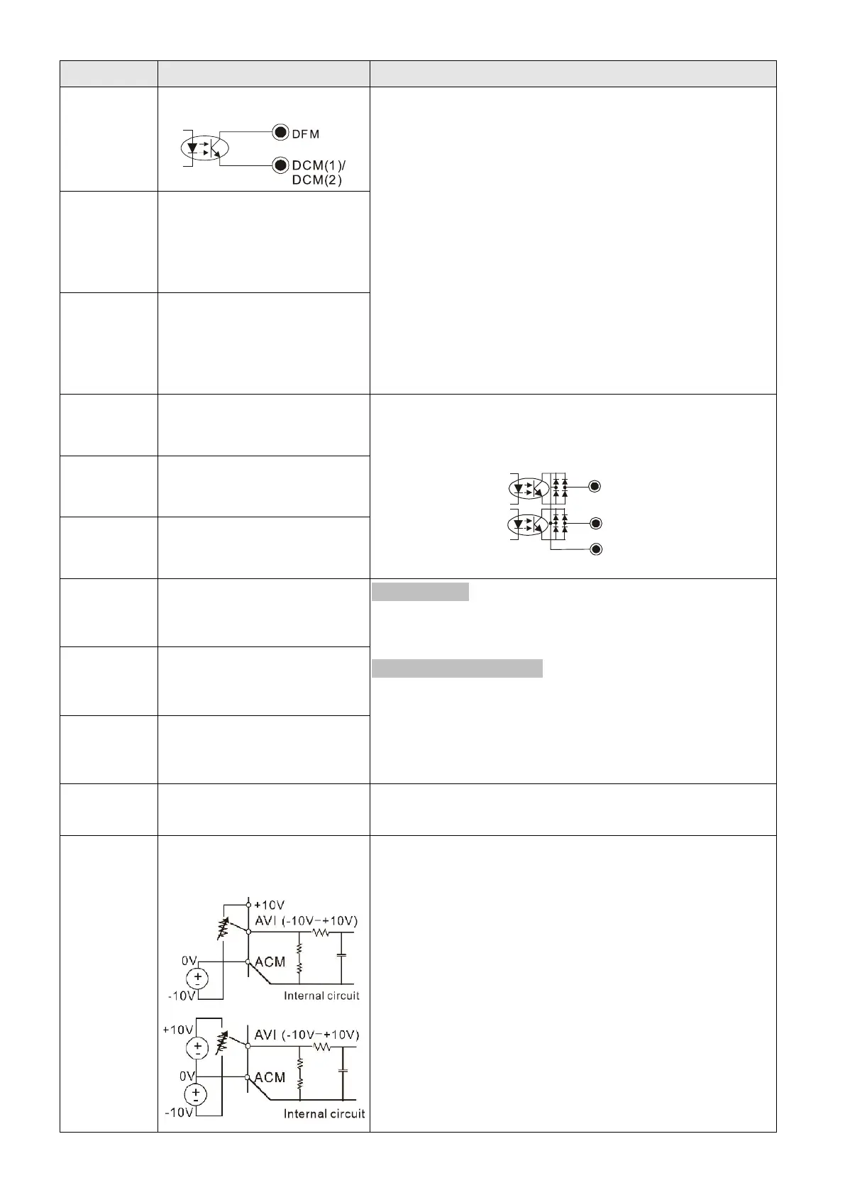
+10 V Potentiometer power supply
Power supply for analog frequency setting:
+10.5±0.5
V
DC
/ 20 mA
AVI
Analog voltage frequency
command
Impedance: 20 kΩ
Range: 0–10 V / -10– +10V = 0–maximum output
frequency (Pr.01-00)
Mode switching by setting Pr.03-00, Pr.03-28
AVI resolution = 12 bits

 Loading...


