Chapter 6 Control TerminalsMH300
Terminals Terminal Function Description
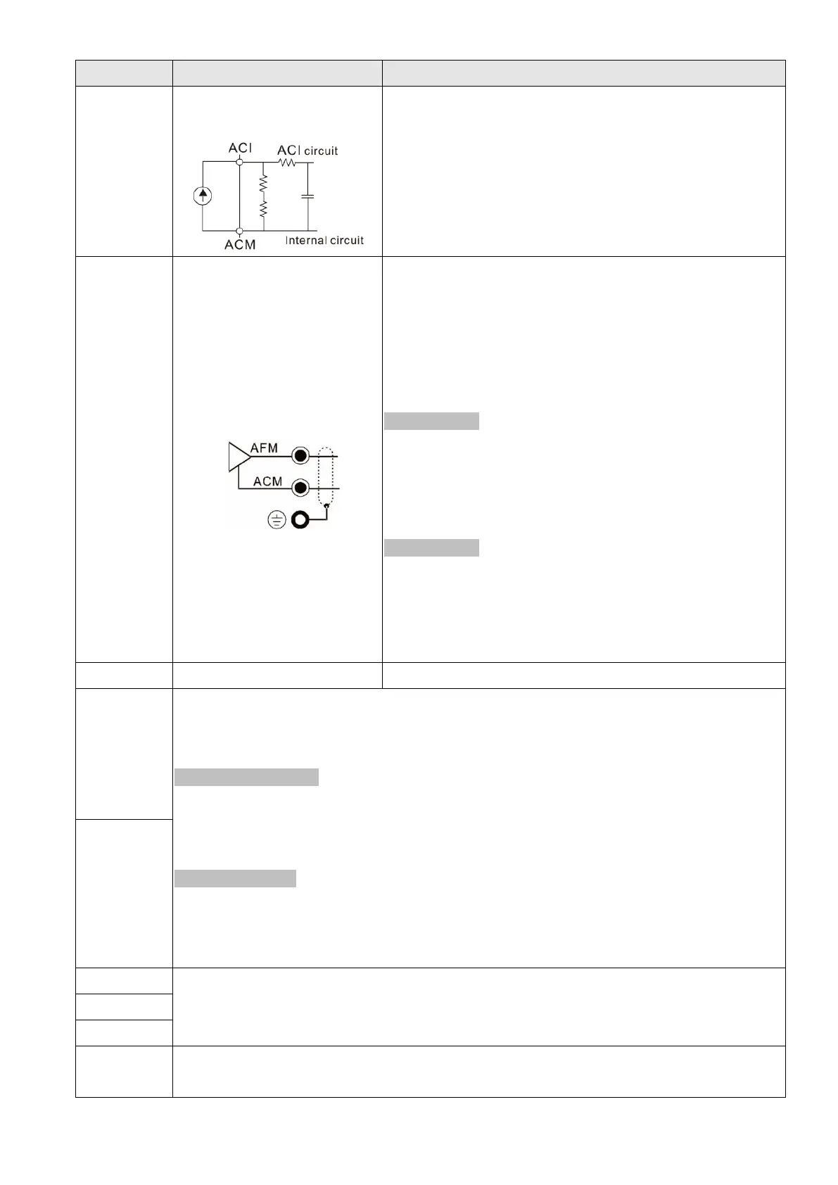
ACI
Analog current frequency
command
Impedance: 250 Ω
Range: 0–20 mA / 4–20 mA / 0–10 V = 0–maximum
output frequency (Pr.01-00)
Mode switching by setting Pr.03-01, Pr.03-29
ACI resolution = 12 bits
AFM
Multi-function analog voltage
output
Switch:
The AFM default is 0–10 V (voltage mode).
Use the switch and Pr.03-31 to change to current mode
(0–20 mA / 4–20 mA). You must follow the indication on
the back side of the front cover or page 6-2 of the user
manual when using the switch.
Voltage mode
Range: 0–10 V (Pr.03-31=0) corresponding to the
maximum operating range of the control object
Maximum output current: 2 mA
Maximum load: 5 kΩ
Current mode
Range: 0–20 mA (Pr.03-31=1) / 4–20 mA (Pr.03-31=2)
corresponding to the maximum operating range of
the control object
Maximum load: 500 Ω
ACM Analog Signal Common Common for analog terminals
S1,S2
Default: S1 / S2 shorted for +24 V
Rated voltage: 24
V
DC
±10%; Maximum voltage: 30
V
DC
±10%
Activation current: 6.67 mA ±10%
STO activation mode
Input voltage level: 0 V
DC
< S1-DCM < 5 V
DC
or 0 V
DC
< S2-DCM < 5 V
DC
STO response time ≤ 20 ms S1 / S2 operates until the AC motor drive stops outputting
current.
STO cut-off mode
Input voltage level: 11 V
DC
< S1-DCM < 30 V
DC
and 11 V
DC
< S2-DCM < 30 V
DC
Power removal safety function according to EN 954-1 and IEC/EN 61508
Note:
refer to user manual Chapter 17 SAFE TORQUE OFF FUNCTION for more details.
DCM
SG+
Modbus RS-485
Note: refer to parameter group 09 of Chapter 12 DESCRIPTION OF PARAMETER
SETTINGS in user manual for more information.
SG-
SGND
RJ45
PIN 1: CAN_H PIN 2: CAN_L PIN 3, 7: SGND PIN 4: SG-
PIN 5: SG+ PIN 6: Reserved PIN 8: +10 VS (provide KPC-CC01 power supply)
Wire size of analog control signals: 0.75 mm
2
(18 AWG) with shielded wire.
Table 6-3

 Loading...


