Chapter 12 Description of Parameter Settings
MH300
Diagram 27
0x6098H
Z Y X
Function Description
Homing
Method
Home
Limit
Z-phase
Signal
Setting
Homing
Mode
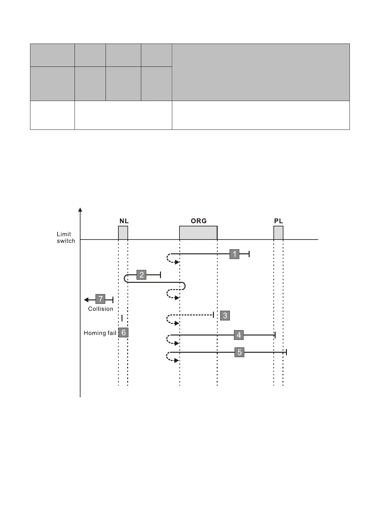
29 No correspondence See the diagram for homing method 29
1. The initial movement is in the reverse direction.
2. When moving in the reverse direction and encountering the negative limit switch, the movement
direction is reversed and waits for the falling-edge trigger of the negative limit switch.
3. When moving in the reverse direction and encountering the falling edge of the ORG switch, the
movement direction is reversed.
4. Then, wait for the rising-edge trigger of the ORG switch as the origin.
A homing failure occurs when the following condition happen:
1. If a positive limit switch signal is encountered when the motor moves in the forward direction, a
homing failure occurs.
2. If no negative limit switch signal is encountered in the homing process mentioned above, and time-
out is triggered, then a homing failure occurs.

 Loading...


