Chapter 16 PLC Function ApplicationsMH300
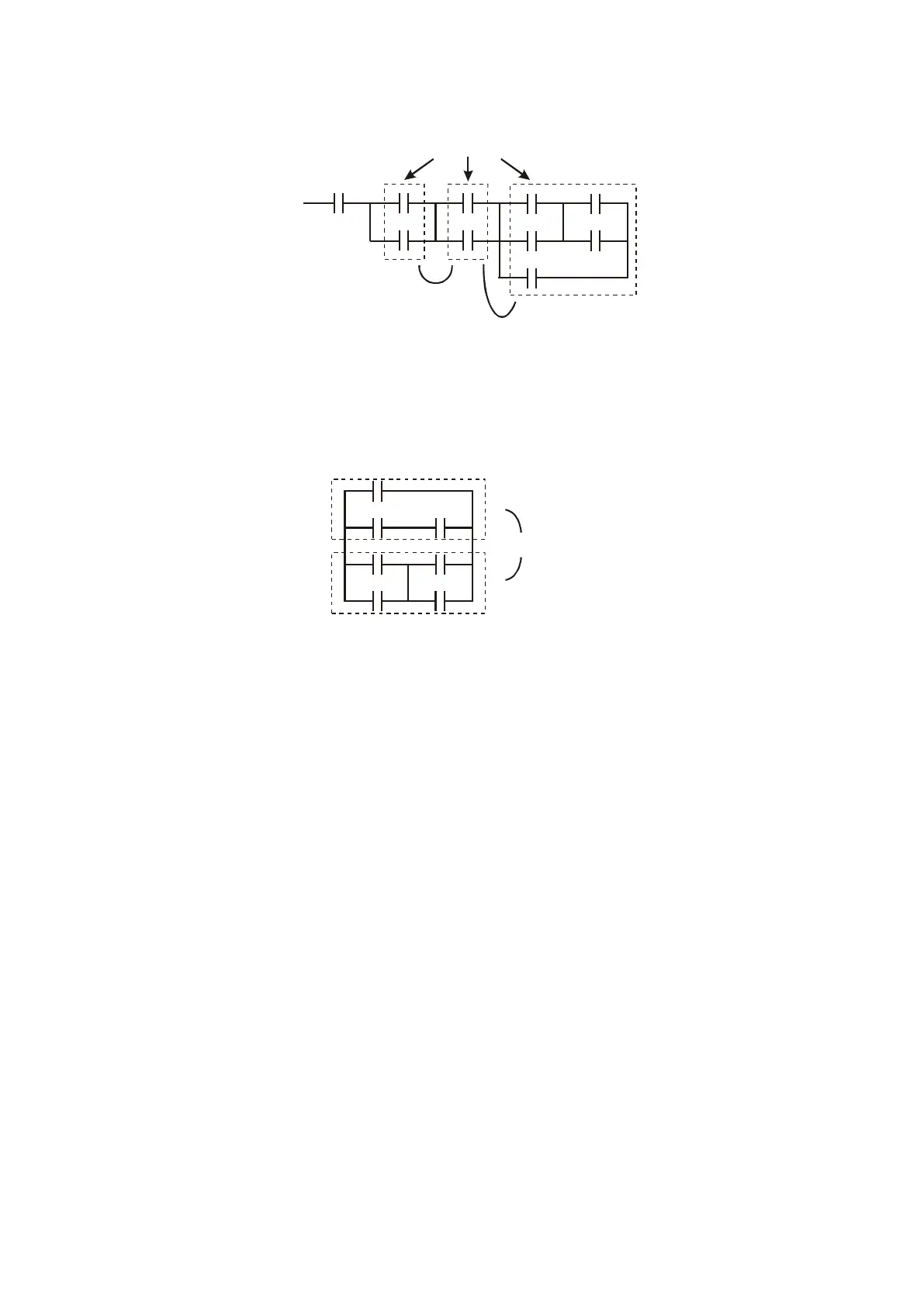
ANB command: a configuration in which one block is in series with one device or block. See Figure
16-34.
Figure 16-34
ORB command: a configuration in which one block is in parallel with one device or block. See Figure
16-35.
Figure 16-35
NOTE:
In the case of ANB and ORB operations that connect a number of blocks, they should be combined
to form a block or network from the top down or from left to right.
MPS, MRD, MPP commands: branching point memory for multiple outputs that enable multiple
different outputs. The MPS command begins at a branching point, which refers to the intersection of
horizontal and vertical lines. Control relies on the contact status along a single vertical line to
determine whether the next contact can give a memory command. While each contact is basically
able to give memory commands, in view of convenience and the PLC’s capacity restrictions, this can
be omitted from some places when editing a ladder diagram. You can use the structure of the ladder
diagram to judge what kinds of contact memory commands are used.
MPS is indicated by use of the ┬ symbol. You can use this command consecutively up to eight times.
The MRD command is read from branching point memory; because logic states along any one vertical
line must be the same, in order to continue analysis of other parts of the ladder diagram, the original
contact status must be read. MRD is indicated by the ├ symbol.
The MPP command is read from the starting state of the uppermost branching point, and it is read
from the stack (pop operation); because it is the final command along a vertical line, it indicates that
the state of the vertical line can be concluded. MPP is indicated by the └ symbol.
Although there should basically be no errors when using the foregoing analytical approach, the

 Loading...


