Chapter 16 PLC Function ApplicationsMH300
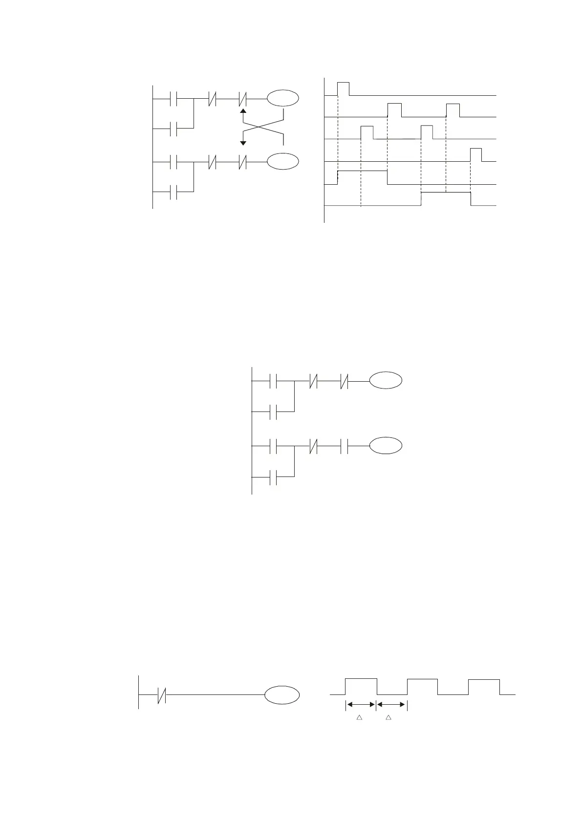
ladder diagram program is scanned from the top down, it is impossible for Y1 and Y2 to
actuate at same time. This ladder diagram assigns priority only to Y1.
Figure 16-41
Example 6: Sequence control
If the N.C. contact of Y2 in the interlocking control configuration from example 5 is put in
series with the Y1 circuit, to create an AND condition for actuation of Y1 (see Figure 16-
42), not only is Y1 a condition for the actuation of Y2 in this circuit, but the actuation of Y2
also stops the actuation of Y1. This configuration confirms the actuation order of Y1 and
Y2.
Figure 16-42
Example 7: Oscillating circuit
Oscillating circuit with a period of ΔT+ΔT
Figure 16-43 shows a very simple ladder diagram. When starting to scan the Y1 N.C.
contact, because the Y1 coil has lost power, the Y1 N.C. contact is closed. When the Y1
coil is then scanned, it is electrified, and the output is 1. When the Y1 N.C. contact is
scanned in the next scanning cycle, because the Y1 coil is electrified, the Y1 NC contact
is open, the Y1 coil then loses power, and the output is 0. Following repeated scanning,
the output of Y1 coil has an oscillating waveform with a period of ΔT(ON)+ΔT(OFF).
Figure 16-43
X1
X3
Y1
Y1
X2
X4
Y2
Y2
Y1
X1
X3
X2
X4
Y1
Y2
Y2

 Loading...


