Chapter 16 PLC Function ApplicationsMH300
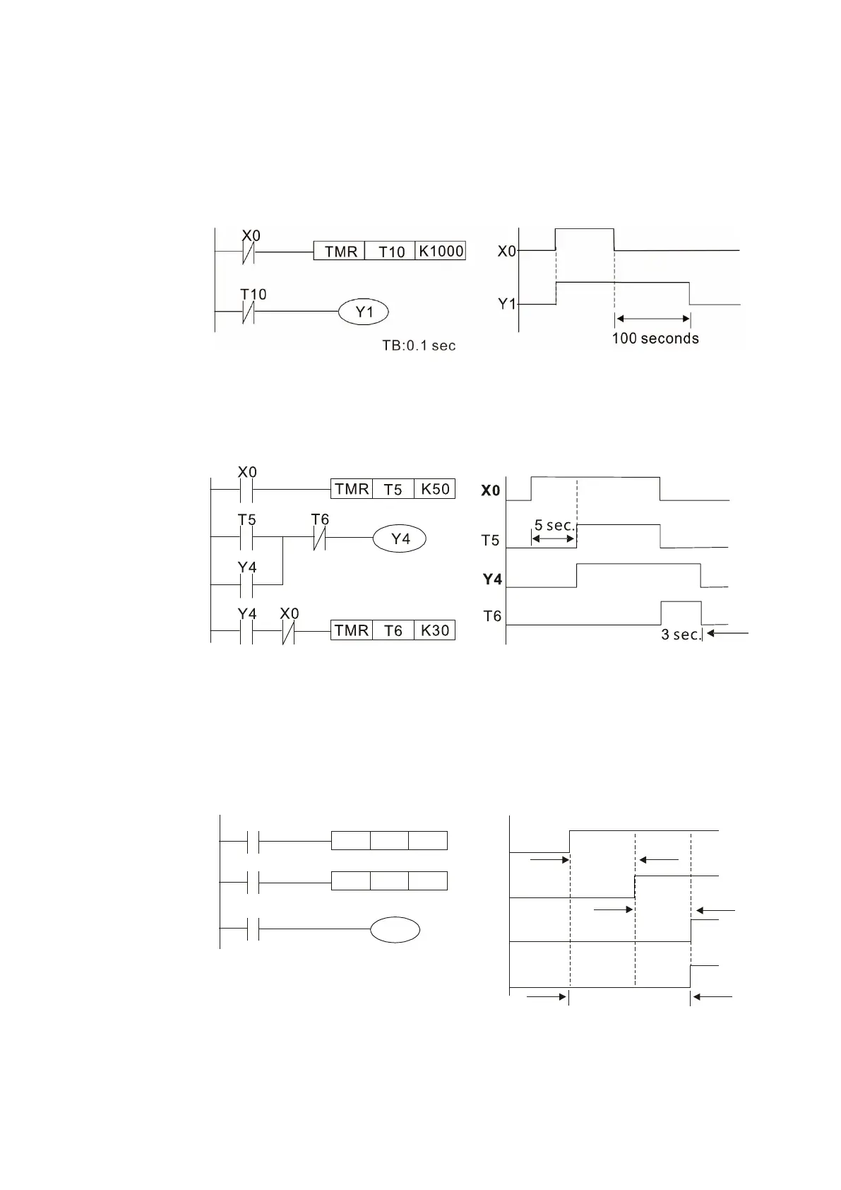
Example 10: Delay circuit
When input X0 is ON, because the corresponding NC contact is OFF, the timer T10 is in
a no power state, and output coil Y1 is electrified. T10 receives power and begins to
count the time only after input X0 is OFF, and output coil Y1 is delayed for 100 seconds
(K1000*0.1 sec. = 100 sec.) before losing power. You can see the sequence of actions
in Figure 16-47.
Figure 16-47
Example 11: The open/close delay circuit is composed of two timers; output Y4 has a delay no matter
input X0 is ON or OFF. See Figure 16-48.
Figure 16-48
Example 12: Extended timing circuit
In the circuit in the ladder diagram (Figure 16-49) on the left, the total delay time from
the moment input X0 closes to the time output Y1 is electrified is (n1+n2)*T, where T is
the clock cycle. The timers are T11 and T12, and the clock cycle is T.
X0
Y1
TMR T12
Kn2
X0
T11
TMR
T11
Kn1
T12
Y1
T11
T
12
n1*T
n2*T
(n1+n2)*T
Figure 16-49

 Loading...


