Chapter 16 PLC Function ApplicationsMH300
Upper differential output
Operand
X0–X17 Y0–Y17 M0–M799 T0–159 C0–C79 D0–D399
-
- - -
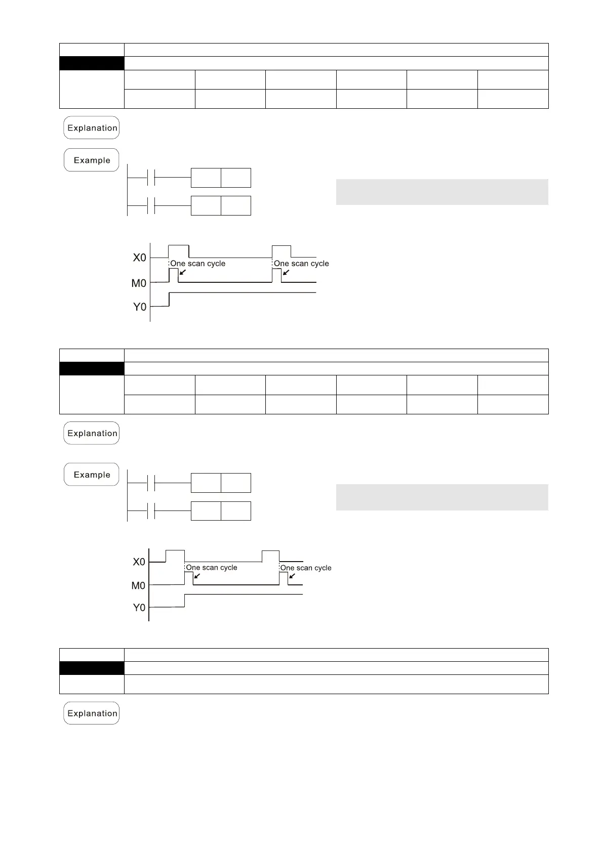
Upper differential output command: when X0 switches from OFF to ON (rising edge-
triggered), the PLS command is executed, and M0 sends one pulse with the
pulse
length consisting of one scanning period.
Timing diagram:
LD X0 Load Contact A of X0
PLS M0
M0 Upper differential
output
LD M0 Load Contact A of M0
SET Y0
Lower differential output
Operand
X0–X17 Y0–Y17 M0–M799 T0–159 C0–C79 D0–D399
-
- - -
Lower differential output command: when X0 switches from ON to OFF (falling edge-
triggered), the PLF command is executed, and M0 sends one pulse with the
pulse
length consisting of one scanning period.
Timing diagram:
LD X0 Load Contact A of X0
PLF M0
M0 Lower differential
output
LD M0 Load Contact A of M0
SET Y0
Operand N/A
An END command must be added to the end of a ladder diagram program or command
program. The PLC scans the program from address 0 to the END command, and
then
returns to address 0 and begins scanning again.

 Loading...


