Chapter 16 PLC Function ApplicationsMH300
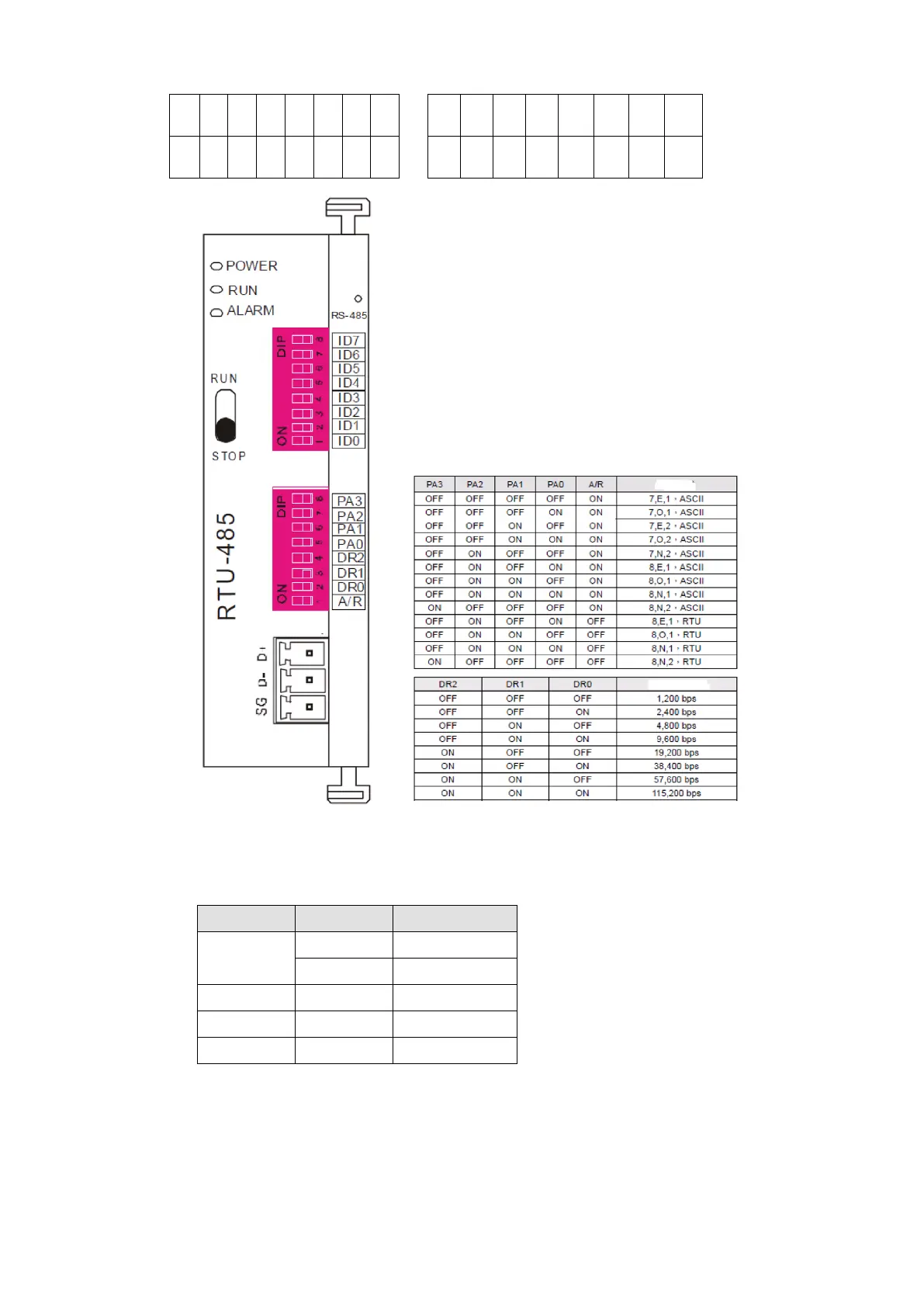
RTU-485: The station number = 8 (give example)
ID7
ID6
ID5
ID4
ID3
ID2
ID1
ID0
PA3
PA2
PA1
PA0
DR2
DR1
DR0
0 0 0 0 1 0 0 0 1 0 0 0 1 1 1 0
Step 2: Install control equipment. We sequentially connect a DVP16-SP (8 IN 8 OUT), DVP-04AD (4
channels AD), DVP02DA (2 channels DA), and DVP-08ST (8 switches) to the RTU-485.
The following corresponding locations can be obtained from the RTU-485's configuration definitions:
DVP16-SP
X0–X7 0400H–0407H
Y0–Y7 0500H–0507H
DVP-04AD
AD0–AD3 1600H–1603H
DVP02DA
DA0–DA1 1640H–1641H
DVP-08ST
Switch 0–7 0408H–040FH
Communication station #:
ID0~ ID7 are defined as 2 , 2 , 2 ...2 , 2
0 1 2 6 7
Communication protocol
Communication Protocol
Communicaton Speed

 Loading...


