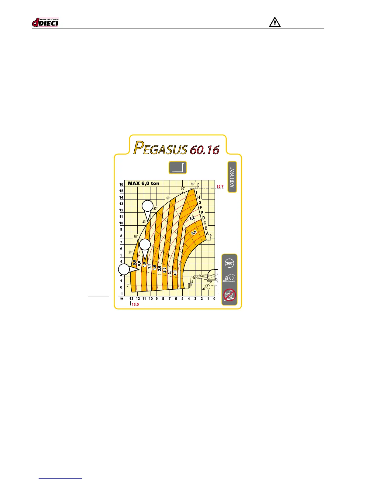
When you know the weight of the load, consult the load table (see the machine technical information sheets in chapter “H“ ) and
nd the section indicating the weight immediately above.
Example:
in the example load table (g.20/C), the weight of the load is 0.9 tons, thus nd the 1.0 ton section (g.20/C Pos.”A”).
The left edge and the upper edge of this section indicate the stability limits of the machine for the load in question.
Do not tilt or extend the boom beyond the limits given. (g.20/C Pos.“B-C“).
After inserting the forks under the load and before lifting the load, check the values on the boom angle and extension indicators.
Example
(With stabiliser feet and rota-
ting turret)
(g.20/B)
C
A
B
As illustrated in the table, the lines start from the graded boom angle and extension scales and go across the section of the table.
Find where the lines regarding the values you are interested in cross. If the cross point is within or on the right of the maximum load
section (known load weight), the load is within safety limits.
If the lines cross above or on the left of the section, do not attempt to lift the load. Retract the boom.
If when the boom is completely retracted, the boom angle and extension values cross outside the maximum load section, do not at-
tempt to lift the load.
When the load is on the forks, retract the boom before lifting or lowering. This will reduce the risk of destabilising the machine.
Note that when the load is raised (for example on scaffolding) it should be released (raised) before retracting the boom completely.
Before putting down a load, consult the load table to determine the maximum distance of the machine from the unloading point.
It must be possible to set down the load without intersecting the limits indicated on the left of or above the maximum load section.