Working basis
22 Service Instructions 867 - 04.0 - 10/2019
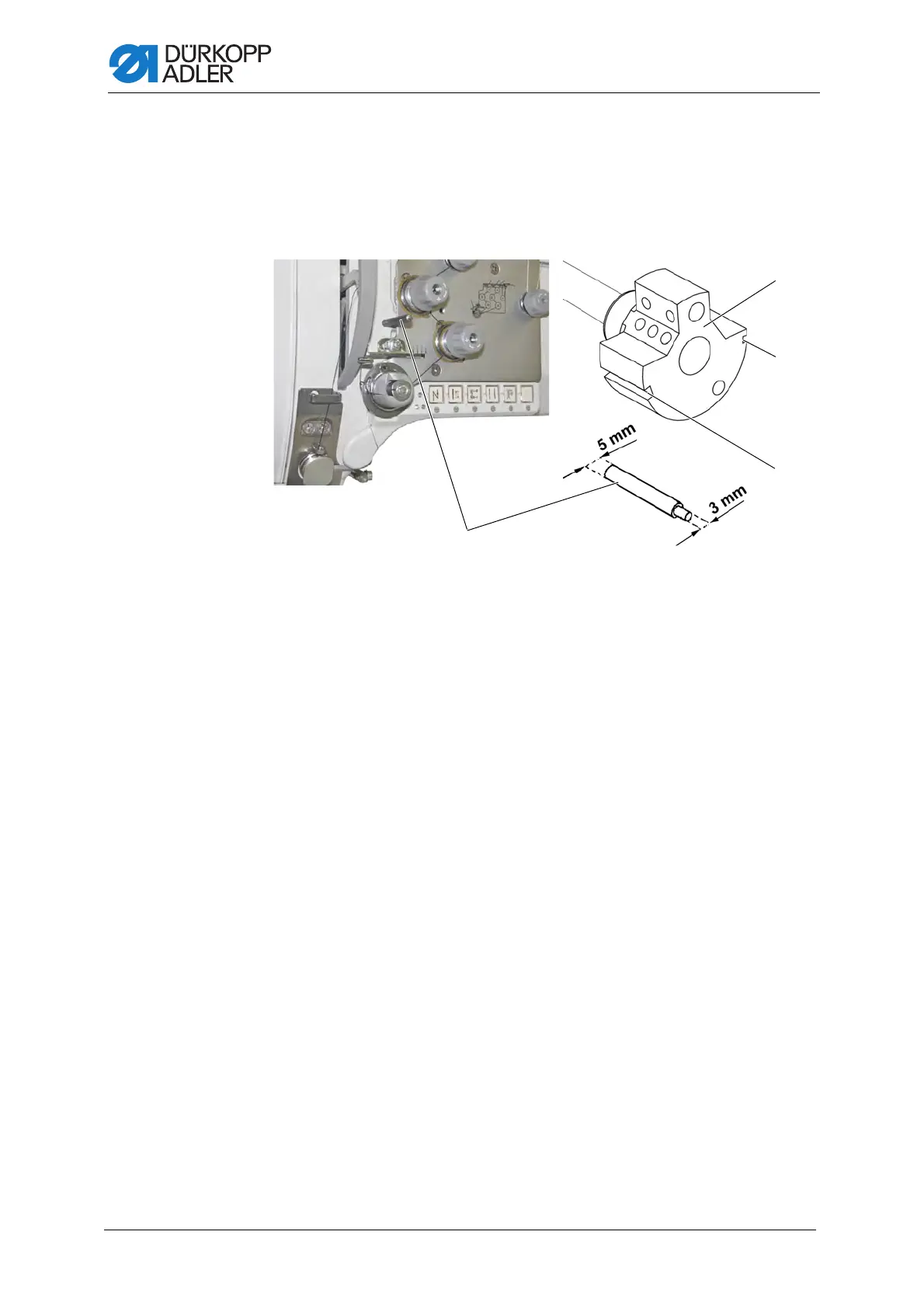
3.5 Locking the machine in place
For some adjustments, the machine must be locked in place. To do this,
the locking peg from the accessory pack is inserted into a slot on the arm
shaft crank, blocking the arm shaft.
Fig. 9: Locking the machine in place (1)
There are 2 securing positions:
• Position 1: Looping stroke position
• 5 mm end in the large slot
• Adjusting the loop stroke and needle bar height
• Position 2: Handwheel zero position
• 3 mm end in the small slot
• Adjusting the handwheel position and checking the top dead center
for the needle bar
(1) - Locking peg
(2) - large arresting groove
(3) - small arresting groove
(4) - Arm shaft crank