SOI 02.10 FV 137/142 599 70 59-01
4.2 - REMOVING THE REAR PANEL (various components and lampholder)
In order to remove the rear panel, simply remove the two upper screws.
Once the rear panel has been removed, the following components are accessible: the lampholder,
the grill heating element, the ignitor, the spit motor, the electronic board, the nozzle support and the
terminal board with cable clamp.
Fig. 283
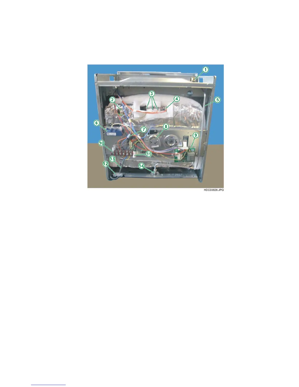
1 - GAS INLET
2 - LAMPHOLDER
3 - GRILL HEATING ELEMENT
4 - SAFETY THERMOSTAT
5 - GAS SUPPLY PIPE
6 - IGNITOR
7 - INTERFERENCE SHIELDING
MAGNET
8 - SPIT MOTOR
9 - ELECTRONIC BOARD
10 - TERMINAL BOARD
11 - INTERFERENCE FILTER
12 - CABLE CLAMP
13 - CONNECTOR CABLE
14 - GAS NOZZLE SUPPORT
4.2.1 - REMOVING THE TERMINAL BOARD
To remove the terminal board, once you have removed the rear panel, please refer to chapter
2.4.4.
4.2.2 - REMOVING THE GRILL HEATING ELEMENT
To remove the grill heating element, once you have removed the rear panel, please refer to chapter
2.4.5.
4.2.3 - REMOVING THE SPIT MOTOR
To remove the spit motor, once you have removed the rear panel, please refer to chapter 2.4.7.
 Loading...