SOI 02.10 FV 51/142 599 70 59-01
2.6.2.10 - VISION ELECTRONIC PYRO VERSION
In the version with Vision Pyro electronic control, after unscrewing the screws fixing the upper
panel, to remove the Control Unit:
1 - Remove the control panel front piece (see chapter 2.3 entitled REMOVING THE CONTROL
PANEL (Fig. 7).
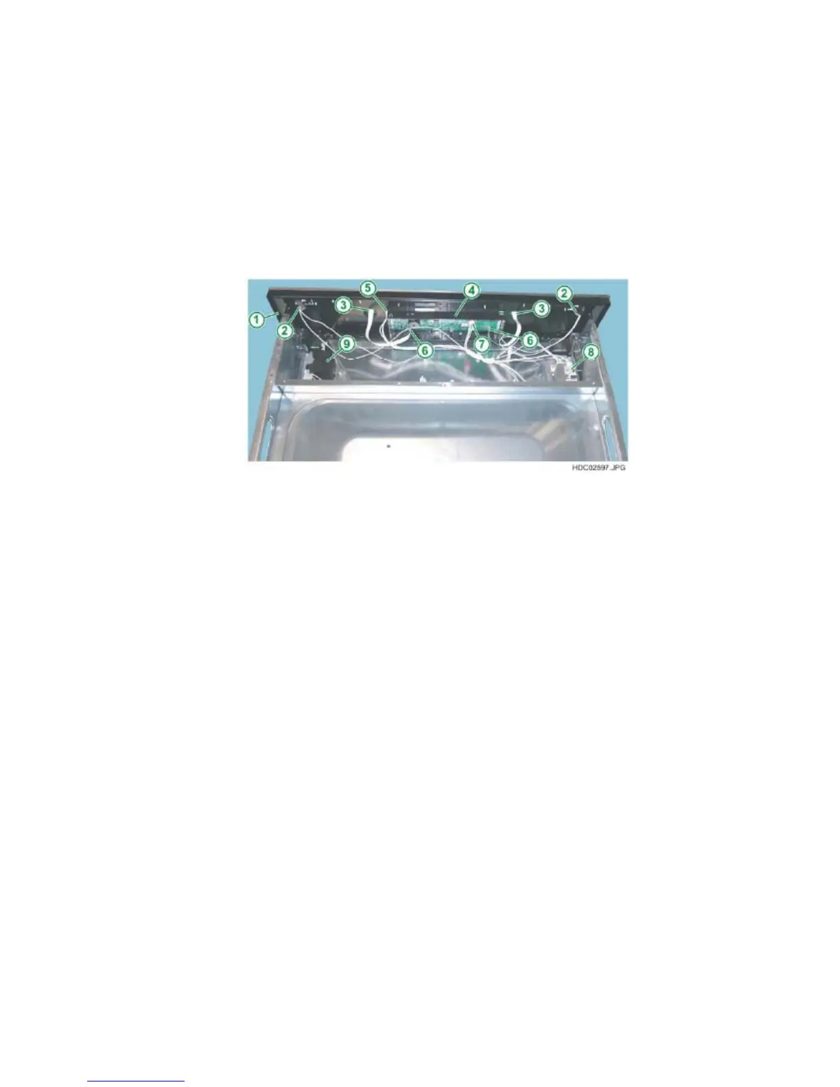
2 - Detach the Control Unit – Power board connection connector (see Fig. 97).
3 - Detach the Control Unit – Touch board connection connectors (see Fig. 97).
4 - Detach the Control Unit – Light Bar board connection connector (see Fig. 97).
5 - Release the retainer hooks positioned in the lower part using a Philips
screwdriver (see Fig. 96).
Fig. 97
1 - CONTROL PANEL
2 - LIGHT BAR CONNECTION CONNECTORS
3 - TOUCH BOARD CONNECTION CONNECTORS
4 - VISION CONTROL UNIT
5 - CONNECTION CONNECTOR TO THE OVC2000 POWER BOARD
6 - CONNECTION CONNECTORS TO TOUCH BOARD
7 - CONNECTION CONNECTOR TO LIGHT BAR BOARD
8 - LIGHT BAR POWER BOARD
9 - DOOR LOCK ASSEMBLY
N.B.: From January 2010 (serial number 001….) access to the top of the oven
has improved thanks to the progressive introduction of a new one-piece top oven
cover (see chapter 2.6.1).
 Loading...