SmartROC T35/T40 20 Automatic Central Lubrication System CLS
128 No: 7026962571.1.7027002891 en-US
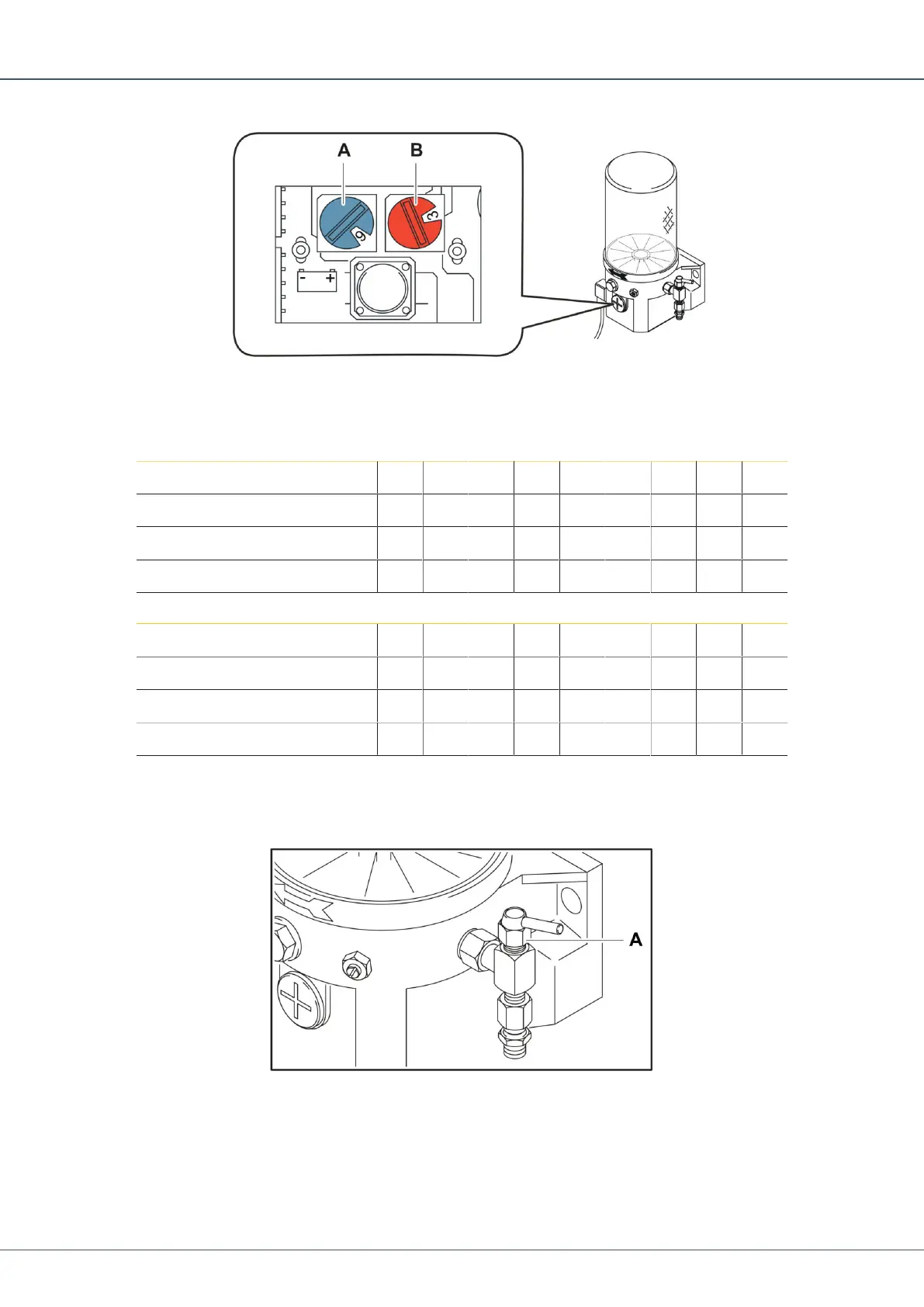
• Pause time can be adjusted to increments of 15 with the blue rotary switch (A). Pause
time is preset from factory.
• Running time can be adjusted to increments of 15 with the red rotary switch (B). Run-
ning time is preset from factory.
Rotary switch position 1 2 3 4 5 6 7 8 9
Hours 1 2 3 4 5 6 7 8 9
Rotary switch position A B C D E F
Hours 10 11 12 13 14 15
Table5: Pause Time Rotary Switch
Rotary switch position 1 2 3 4 5 6 7 8 9
Minutes 2 4 6 8 10 12 14 16 18
Rotary switch position A B C D E F
Minutes 20 22 24 26 28 30
Table6: Running Time Rotary Switch
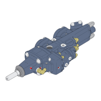
20.3 Lubrication Pump Safety Valve
Location of Safety Valve on Lubrication Pump
The safety valve (A) is used to limit the pressure in the system. The valve opens at a pres-
sure of .
If a hose, lubrication point, or nipple is blocked, the lubricant grease leaks out of the safety
valve. Troubleshooting is required when it happens.
 Loading...