SmartROC T35/T40 22 Service Tool Bag RCS
146 No: 7026962571.1.7027002891 en-US
è
The multimeter reads 24 ±1 V.
If the valve is not activated, there can be an open circuit in the cable running to the
valve or in the coil in the valve.
Pin Function
1 +24 V DC
2 Signal B
3 Ground
4 Signal A
5 Ground
Table16: Pin Configuration
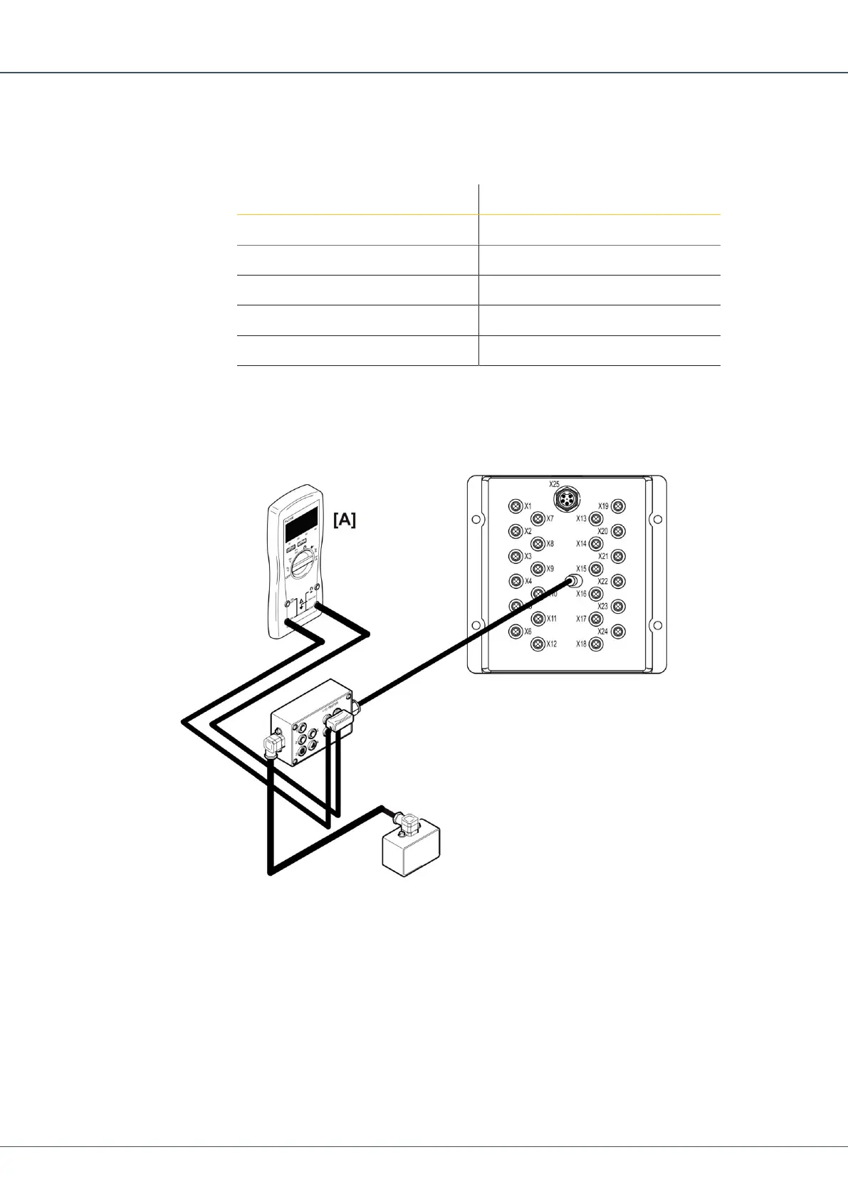
22.6 Checking Digital Outputs Current on I/O Module
Each designated contact has two digital outputs, A and B.
1.
Connect the 5-position connector on the I/O tester between the output of interest on
the I/O module and the valve.
2.
Connect the multimeter in series with the +A or +B output.
3.
Activate the function.
è
The multimeter reads 1 A.
If the multimeter reads 0.00 A and the solenoid coil diode comes on, there could be
an open circuit in the valve coil.
 Loading...