SmartROC T35/T40 22 Service Tool Bag RCS
149 No: 7026962571.1.7027002891 en-US
22.10 Checking Resolver Module Resolver Inputs
For the inputsX6 - X9 there are designated contacts.
1.
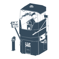
Connect the resolver tester to the relevant cable. Turn the test sensor slowly and
check that the angle shown on the sensor menu changes.
a.
If the angle changes, the sensor on the boom is faulty.
b.
If the angle does NOT change, the cable on the boom must be checked.
2.
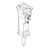
Connect the test sensor and test cable directly to the resolver module input. Turn the
test sensor slowly and check that the angle on the sensor menu changes.
a.
If the angle changes, the cable on the boom is faulty
b.
If the angle does NOT change, the resolver module is faulty.
Pin Function
1 Ref +
2 Ref -
3 Sine Signal
4 Sine Ground
5 Cosine Signal
6 Cosine Ground
Table19: Pin Configuration
22.11 Checking Resolver Module Encoder Inputs
There is a designated contact, X10, for the pulse sensor.
1.
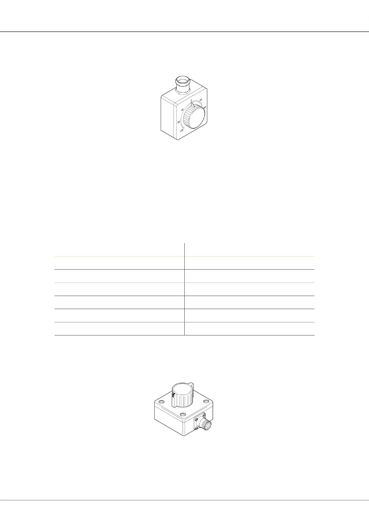
Connect the encoder tester to the relevant cable. Turn the test sensor slowly and
check that the length measurement shown on the sensor menu changes.
a.
If the measured value changes, the sensor on the boom is faulty.
 Loading...