SmartROC T35/T40 22 Service Tool Bag RCS
144 No: 7026962571.1.7027002891 en-US
2.
Connect the 5-pin connectors of the tester to the CAN network requiring measure-
ment:
a.
Decoder: contact X3 or X4
b.
Display, application, and master modules: connector X2, X3, or X4
c.
I/O modules: contact X1 or X19
d.
Resolver modules: contact X3 or X4
3.
Select cable test on the CAN tester.
è
The multimeter reads about 60–65 Ohms if the cable is intact.
The multimeter reads 120 Ohms if the end plug is missing or there is a break in
a cable.
!
NOTE: Because of the internal resistance in the tester, the
multimeter reads about 100 kOhm if the cables are not con-
nected or if there is an open circuit.
22.4 Checking Digital Inputs on I/O Module
Each designated contact has two digital inputs, A and B.
1.
Connect the 5-position connector on the I/O tester between the input of interest on the
I/O model and the guard.
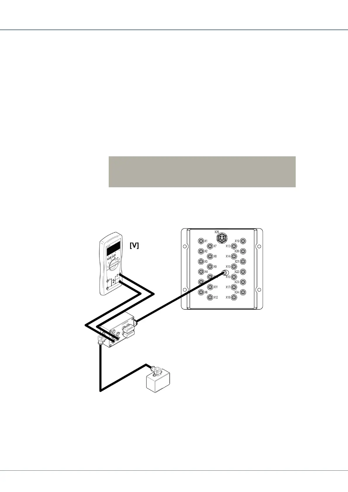
2.
Connect the multimeter between ground and the signal A (+A) or signal B (+B) output
of interest.
3.
Measure the voltage according to the table.
 Loading...