SmartROC T35/T40 22 Service Tool Bag RCS
147 No: 7026962571.1.7027002891 en-US
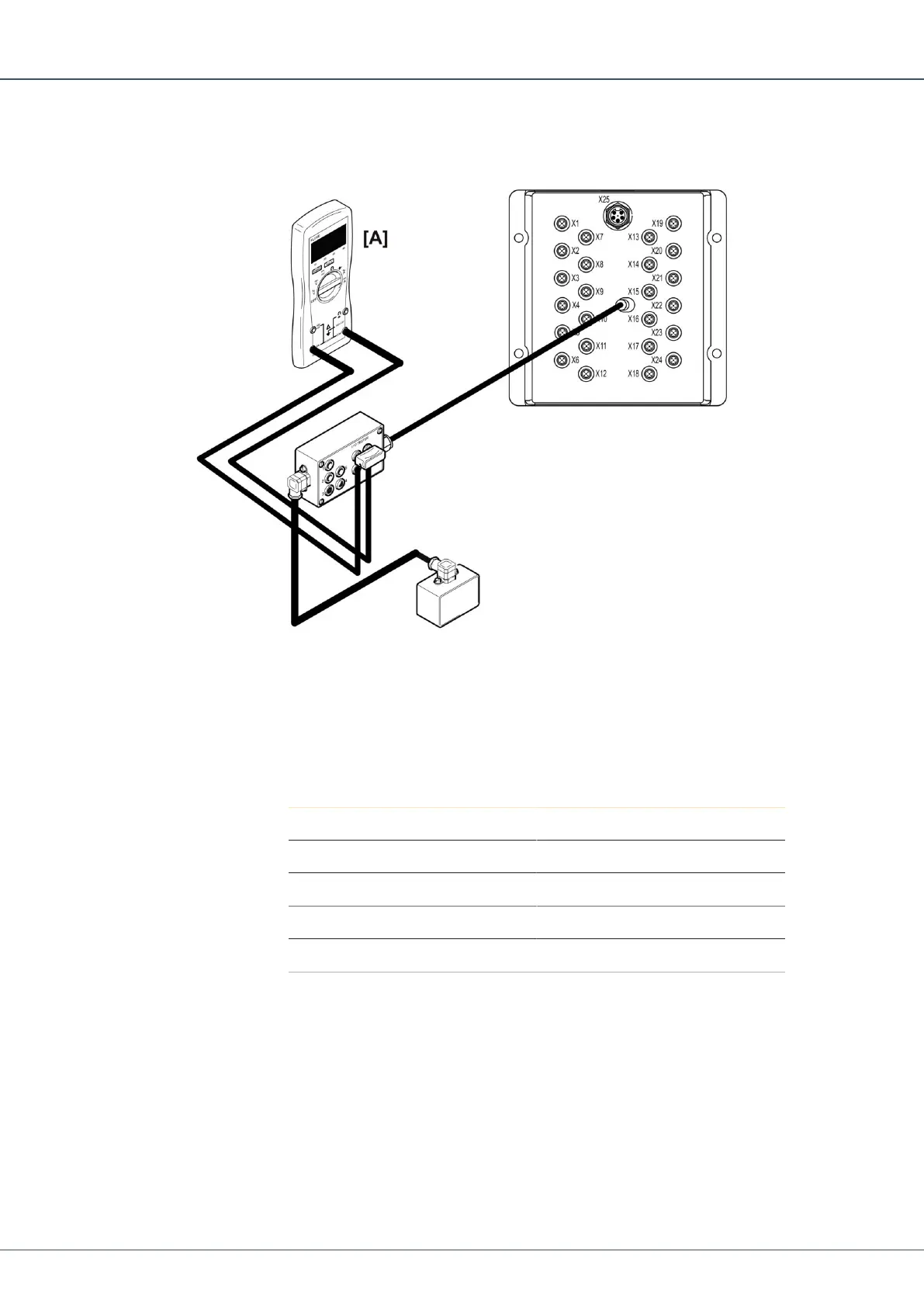
22.7 Checking PWM Outputs Current on I/O Module
Each designated contact has two PWM outputs, A and B.
1.
Connect the 5-position connector on the I/O tester between the output of interest on
the I/O module and the valve.
2.
Connect the multimeter in series with the +A or +B output that is of interest.
3.
Activate the function.
4.
Check that the current corresponds with the actuated value on the display.
è
Pin Function
1 Not Used
2 Out +B
3 Out -B
4 Out +A
5 Out -A
Table17: Pin Configuration
22.8 Checking Analog Inputs on I/O Module
Each designated contact has one analog input.
 Loading...