SmartROC T35/T40 15 Electrical System
95 No: 7026962571.1.7027002891 en-US
13.
Disconnect the battery chargers negative cable from the negative terminal on battery
(B).
14.
Disconnect the battery chargers positive cable from the positive terminal on battery
(B).
15.
Connect the jumper lead between the negative terminal on battery (B) and the posi-
tive terminal on battery (A).
16.
Connect the cable between chassis ground and the negative terminal on battery (A).
17.
Turn on the battery isolation switch.
15.7 Starting with Auxiliary Battery
WARNING
Risk of Explosion
There is a risk of personal injury if a charged battery is connected to a discharged bat-
tery.
u Use a well ventilated area.
u Fire extinguisher must be close at hand.
u Use protective safety glasses.
u Use protective gloves.
Precondition
p
The RCS system on the control system panel is turned off.
p
The fire suppression system is disconnected.
1.
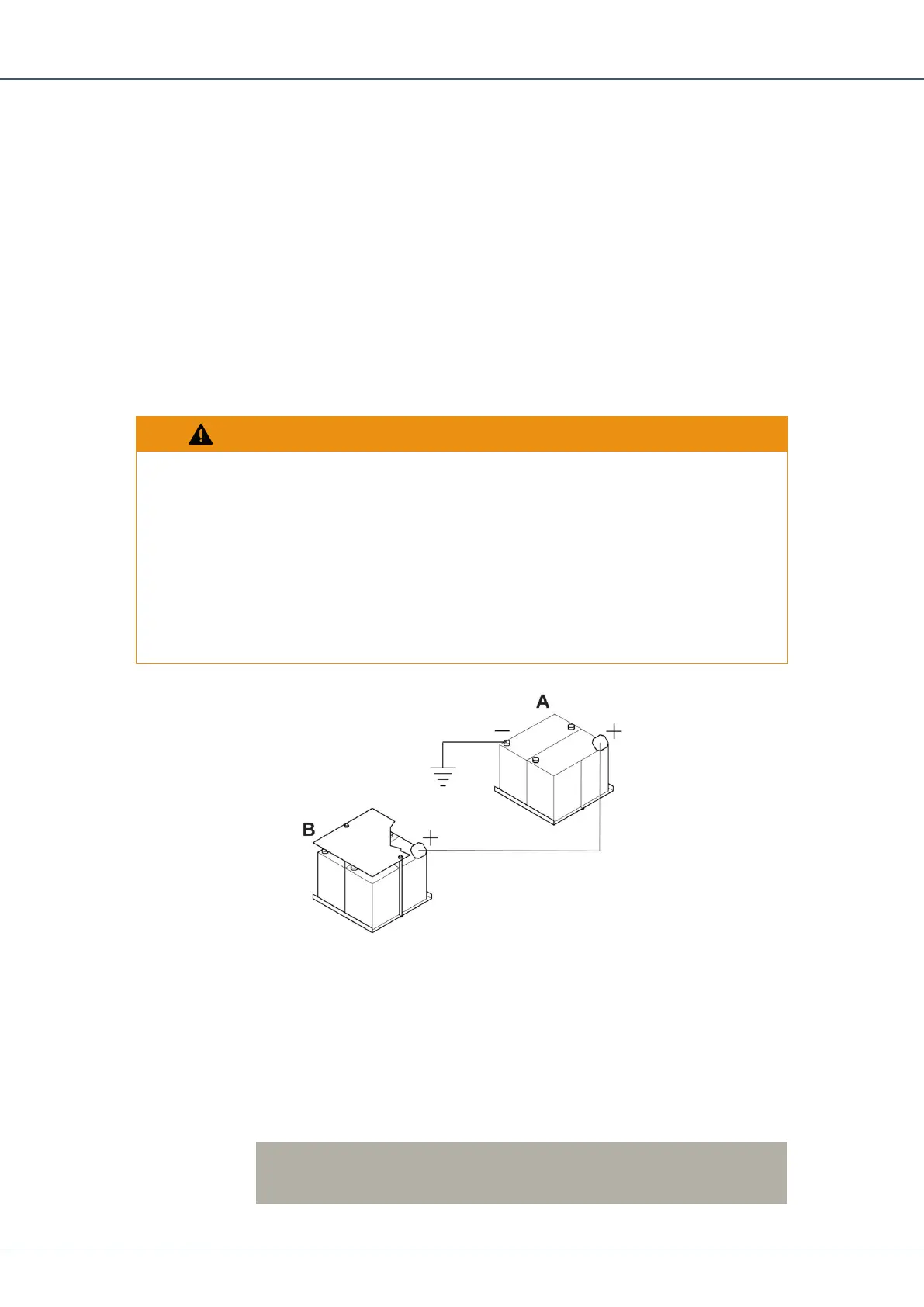
Check that the auxiliary batteries (A) have the same voltage as the chassis batteries
(B).
2.
Connect the positive terminal of the auxiliary batteries (A) to the positive terminal of
the chassis batteries (B).
3.
Connect the negative terminal of the auxiliary batteries (A) to ground on the chassis.
!
NOTE: Do not connect the negative terminal of the auxiliary batter-
ies (A) to the chassis batteries (B) negative terminal.
 Loading...