SmartROC T35/T40 22 Service Tool Bag RCS
150 No: 7026962571.1.7027002891 en-US
b.
If the measured value does NOT change, the cable on the boom must be
checked.
2.
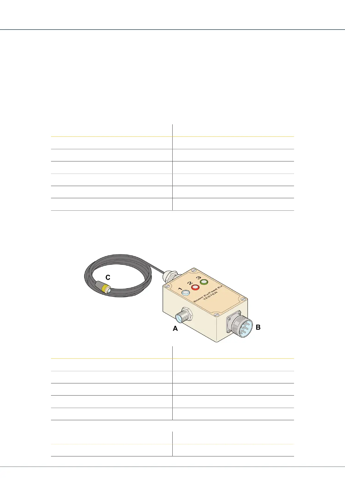
Connect the test sensor with test cable directly to the resolver module input. Turn the
test sensor slowly and check that the length measurement shown on the sensor menu
changes.
a.
If the measured value changes, the cable on the boom is faulty.
b.
If the measured value does NOT change, the resolver module is faulty.
Pin Function
1 + 15V
2 + 15V
3 Signal A
4 Ground
5 Signal B
6 Ground
Table20: Pin Configuration
22.12 Checking Resolver Module Analog Inputs
There are two designated connectors, X11 and X12, for analog input.
Pin Function
1 Ground
2 + 4.5-V DC power supply out
3 Signal in
4 Not Used
5 Not Used
Table21: Pin Configuration for Input X11
Pin Function
1 Ground
 Loading...