SmartROC T35/T40 22 Service Tool Bag RCS
148 No: 7026962571.1.7027002891 en-US
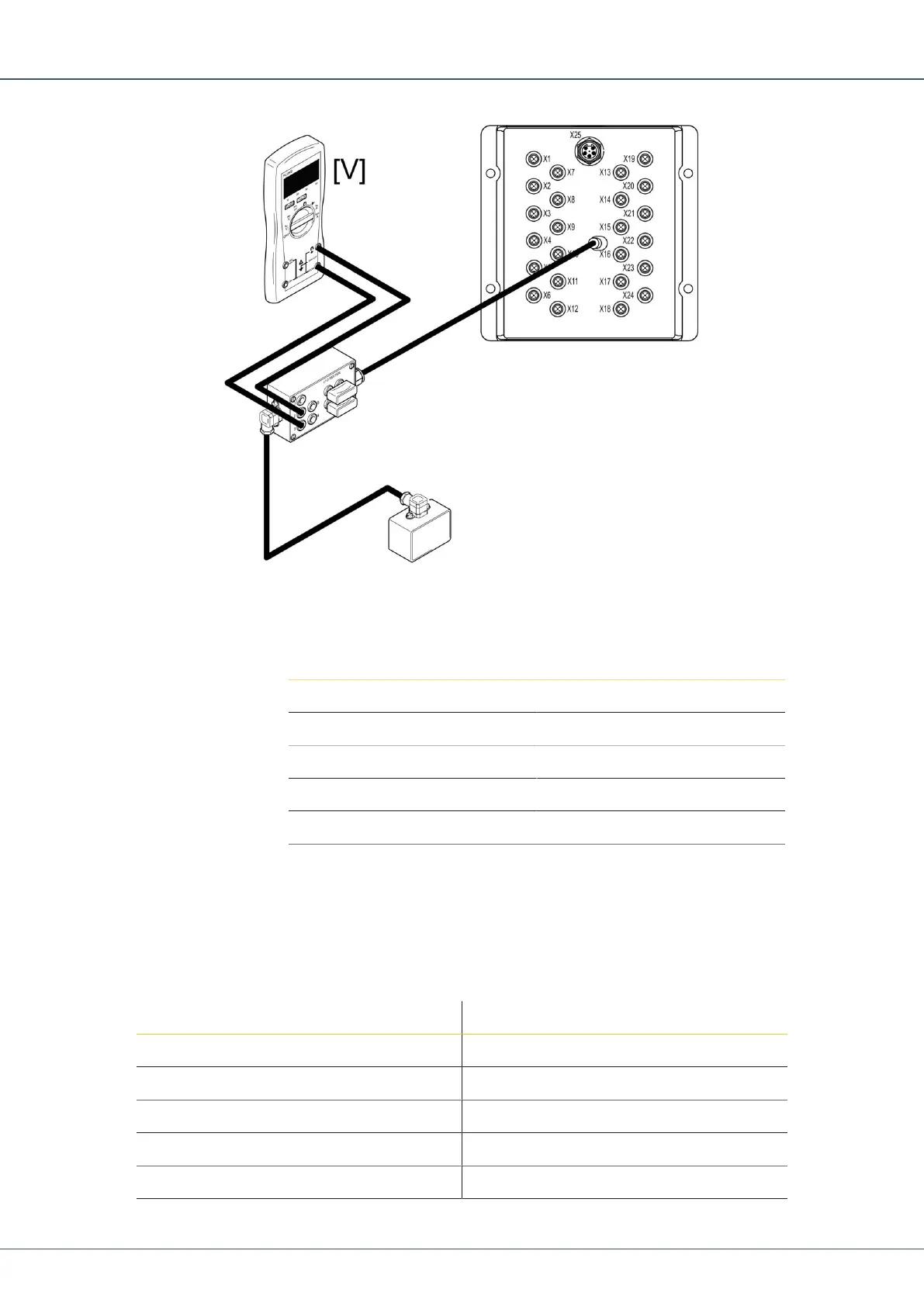
1.
Connect the 5-position connector on the I/O tester between the input of interest on the
I/O model and the sensor.
2.
Measure the values according to the table.
è
Pin Function
1 +24 V DC
2 0–5 V
3 Ground
4 4–20 mA
5 +5 V DC
Table18: Pin Configuration
22.9 Encoder Inputs
Each encoder connector has two signals, A and B.
There are two designated contacts, X12 and X18, for the pulse sensor.
Pin Function
1 +24 V DC
2 B
3 Ground
4 A
5 Ground
 Loading...