SmartROC T35/T40 22 Service Tool Bag RCS
143 No: 7026962571.1.7027002891 en-US
22.3 Checking CAN Cable
The power supply for the module, the CAN power supply and the CAN communication can
be measured and checked using the CAN test equipment.
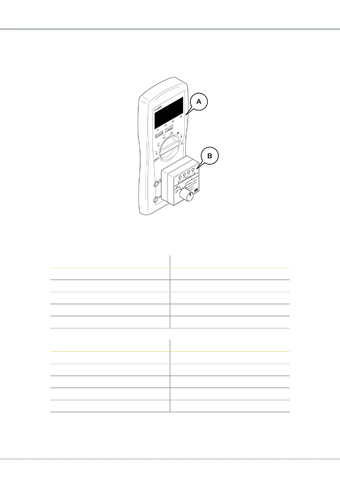
CAN Test Equipment
Connect the CAN tester (B) on the multimeter (A). Make certain the pins are positioned
correctly as indicated by the colour coding. The red pin goes to V/Ohm on the multimeter.
Always use the torque tools to tighten cable connections.
Pin Function
1 Screen/Shield
2 CAN +
3 CAN -
4 CAN Hi
5 CAN Low
Table13: Pin Configuration, CAN Inputs and Outputs, I/O Modules
Pin Function
1 NC/Not Connected
2 CAN +
3 CAN -
4 CAN Hi
5 CAN Low
Table14: Pin Configuration, CAN Inputs and Outputs, Other Modules
Precondition
p
The RCS is shut down.
1.
Set the multimeter measuring range to ohms.
 Loading...