SmartROC T35/T40 22 Service Tool Bag RCS
142 No: 7026962571.1.7027002891 en-US
CAN Test Equipment
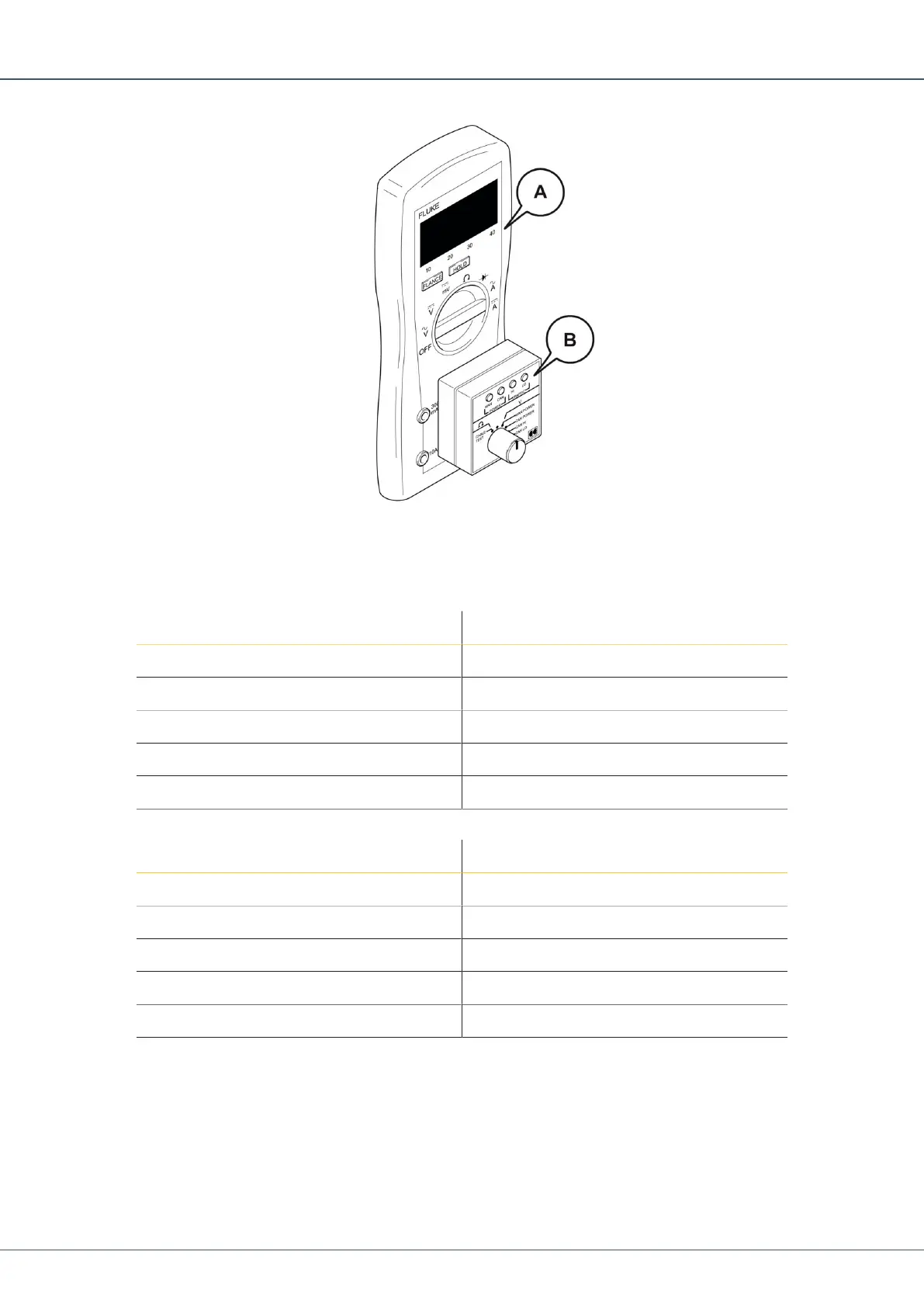
Connect the CAN tester (B) on the multimeter (A). Make certain the pins are positioned
correctly as indicated by the colour coding. The red pin goes to V/Ohm on the multimeter.
Always use the torque tools to tighten cable connections.
Pin Function
1 Screen/Shield
2 CAN +
3 CAN -
4 CAN Hi
5 CAN Low
Table11: Pin Configuration, CAN Inputs and Outputs, I/O Modules
Pin Function
1 NC/Not Connected
2 CAN +
3 CAN -
4 CAN Hi
5 CAN Low
Table12: Pin Configuration, CAN Inputs and Outputs, Other Modules
1.
Set the multimeter range to DC volt.
2.
Connect the 5-pin connector of the tester to the power supply of the module.
a.
I/O modules: contact X25. 7-pin contact. Use enclosed T-cross.
b.
Other modules: connector X1. 4-pin connectors.
è
The power supply (main power) is between 24–28 V (lights green).
 Loading...