3. Replacing the Cable Unit Part 2: Maintenance
96
(10) Referring to the Wiring Schematic 1 in this chapter, disconnect the ground wires and
pneumatic tubes from the arm. To disconnect each pneumatic tube, pull it out by first
pushing the fitting release ring. The ground wire terminals are secured by bolts
(M4
×
8).
(11) Referring to the wiring schematics in this chapter, disconnect the connectors from the
base and arm. To disconnect the power connector, pull it out while pushing the
presser tongue next to the connector number on the motor side.
For manipulators whose serial number start with “1,” their motors must be connected
to the signal relay board of the new cable unit within 2 hours. Otherwise, the motor
will lose the position data and it is necessary to calibrate again.
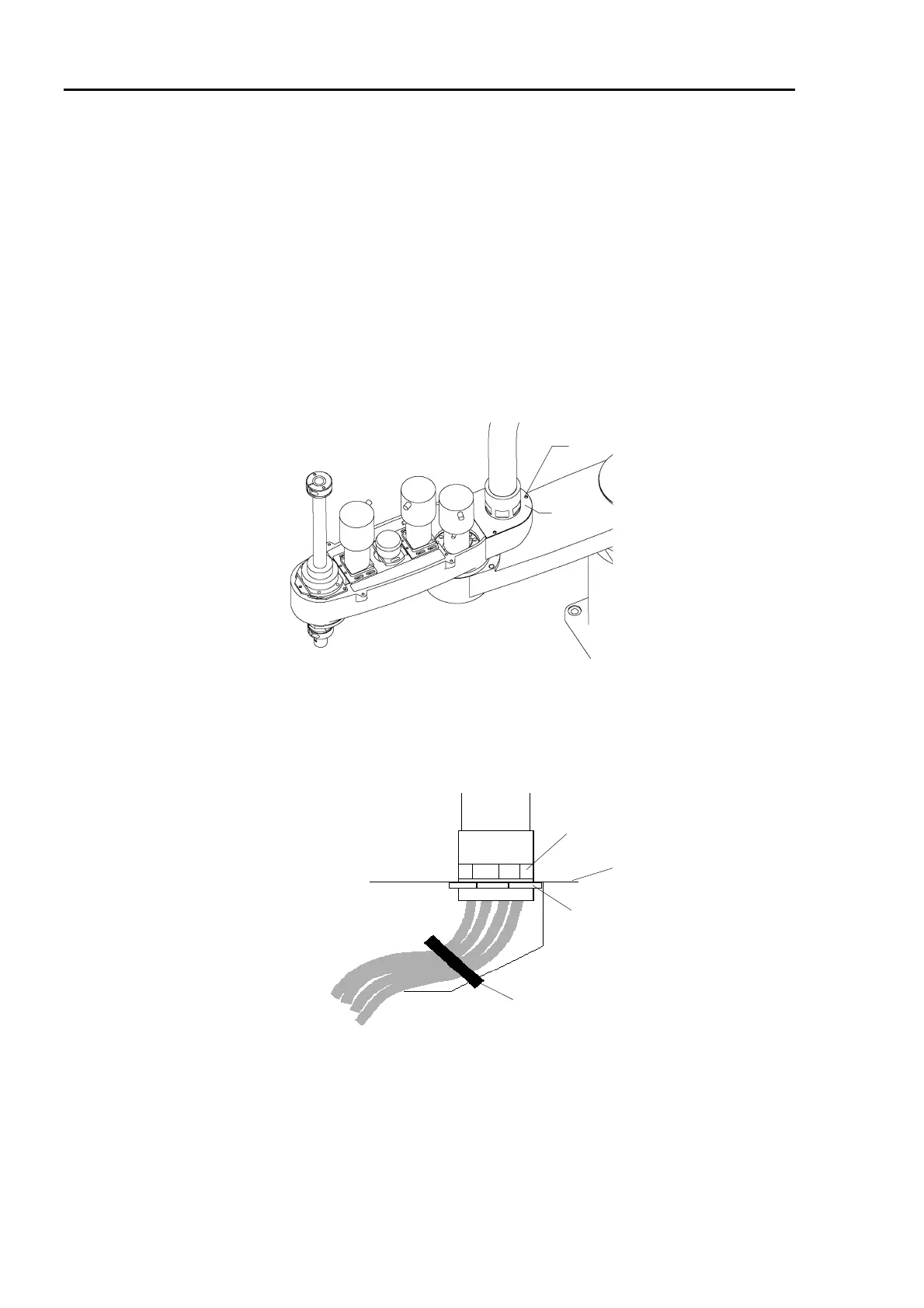
(12) Remove the cable bracket from the arm (3-M4
×
8 bolts).
M4×8
Cable bracket
(13) Cut off the wire tie binding cables to the cable bracket.
(14) Remove the joint from the nut. Pull the cables out of the cable bracket and nut. The
nut is hitting the back of the cable bracket at the corner, preventing it self from
rotating.
Nut
Duct joint
Cable bracket
(13) Wire tie
(15) If there are any wire ties binding the cables, cut them off. Remove the cable unit.
NOTE
 Loading...


