Part 2: Maintenance 4. Connector Pin Assignments
103
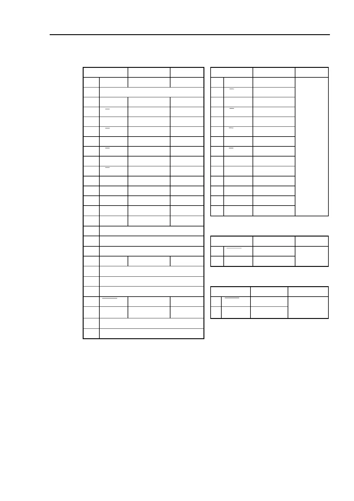
X30 Signal connector X31 Motor signal connector
No. Line color Connect to No. Line color Connect to
1A FGND GRN shield 1 3A BLU/(WHT)
1B N.C. 2 3A WHT/(BLU)
2A 3A BLU/(WHT) X31-1 3 3B YLW/(WHT)
2B 3A WHT/(BLU) X31-2 4 3B WHT/(YLW)
3A 3B YLW/(WHT) X31-3 5 3Z GRN/(WHT)
3B 3B WHT/(YLW) X31-4 6 3Z WHT/(GRN)
4A 3Z GRN/(WHT) X31-5 7 3S * RED/(WHT)
4B 3Z WHT/(GRN) X31-6 8 3S * WHT/(RED)
5A 3S * RED/(WHT) X31-7 9 BAT+ BLU/(BRN)
5B 3S * WHT/(RED) X31-8 10 BAT- BRN/(BLU)
6A ENC+5V PPL/(WHT) X31-12 11 RES YLW/(BRN)
6B EGND WHT/(PPL) X31-13 12 ENC+5V PPL/(WHT)
7A BAT+ BLU/(BRN) X31-9 13 EGND WHT/(PPL)
7B BAT- BRN/(BLU) X31-10 14 FGND GRN
Joint #3
motor
encoder
(SIGNAL)
8A RES YLW/(BRN) X31-11
8B N.C.
X32 brake connector
9A N.C. No. Line color Connect to
9B N.C. 1 EMB2 GRN/(BRN)
10A BRK.SW BRN/(YLW) X33-2 2 +24V BRN/(GRN)
Joint #3
brake (Y1)
10B N.C.
11A N.C.
X33 brake SW connector
11B N.C. No. Line color Connect to
12A EMB2 GRN/(BRN) X31-2 1 EMB2 GRN
12B +24V BRN/(GRN) X32-2 2 BRK.SW BRN/(YLW)
Joint #3 brake
release
button (S1)
13A N.C.
13B N.C.
* Motor for the manipulators whose Serial
number starts with “1” does not have
S-channel signal.
 Loading...


